


IMPORTANT ELECTRICAL INFORMATION (Long!)

Intermediate

Joined: Aug 2012
Posts: 29
Likes: 0
Many of you have asked me for help on solving electrical problems and I thought this would be VERY interesting!
My 98 coupe would get the infamous "REDUCED ENGINE POWER", "TRACTION CONTROL FAILURE" and a host of random failure codes. After many, many hours of troubleshooting, replacing the BCM and TAC module, I solved most of the driveability issues. Still getting the random DTC failure codes, I thought that I may be having ground issues. Back in June I cleaned ALL of the chassis grounds and the car virtually stopped throwing the "RANDOM" DTC failure codes. Just moving the wires in the chassis ground connector was enough to change the indications and make the issues stop happening.
I had a chance to speak with some GM C5 Trouble Desk Engineers when I went to Bowling Green KY in April and they pointed out that MANY of the C5 electrical issues can be directly linked to chassis ground problems. The engineer even went as far as to recommending that I chop off the factory under hood chassis ground connectors and combine all of the wires into a single ground lug. Not wanting to just LOP off the factory connector, I took a chance and disassembled one of the ground plug connectors and to my surprise it was indeed full of corroded connections.
I strongly recommend that any C5 owner that has had or who are having electrical issues, examine and clean the chassis ground connectors. This may save you from needlessly replacing expensive electronics modules. Each ground connector can be disassembled and cleaned in about 20 min.
Just cleaning the metal ground connection between the chassis and the plug is only a band aid solution. Now that I look back, when I cleaned my chassis grounds and initially solved my issues, I believe that when the connector is being removed to clean the connection between chassis and the connector, just the wires being moved inside the plug is what changed the indications and made everything work better.
Disassembly of the chassis ground plug and cleaning the contacts inside the connector is the correct method of solving the issue!
I took some pictures of the under hood chassis ground connector and the corrosion that was in it. I cleaned the two connections on the frame rails and the left one was significantly corroded! Taking it apart and cleaning it is a very straight forward procedure and I believe that if you follow this recommendation, you will be on the way to solving the many of the electrical issues.
Here are some detailed pictures of the ground connector and the corrosion that was found inside it!
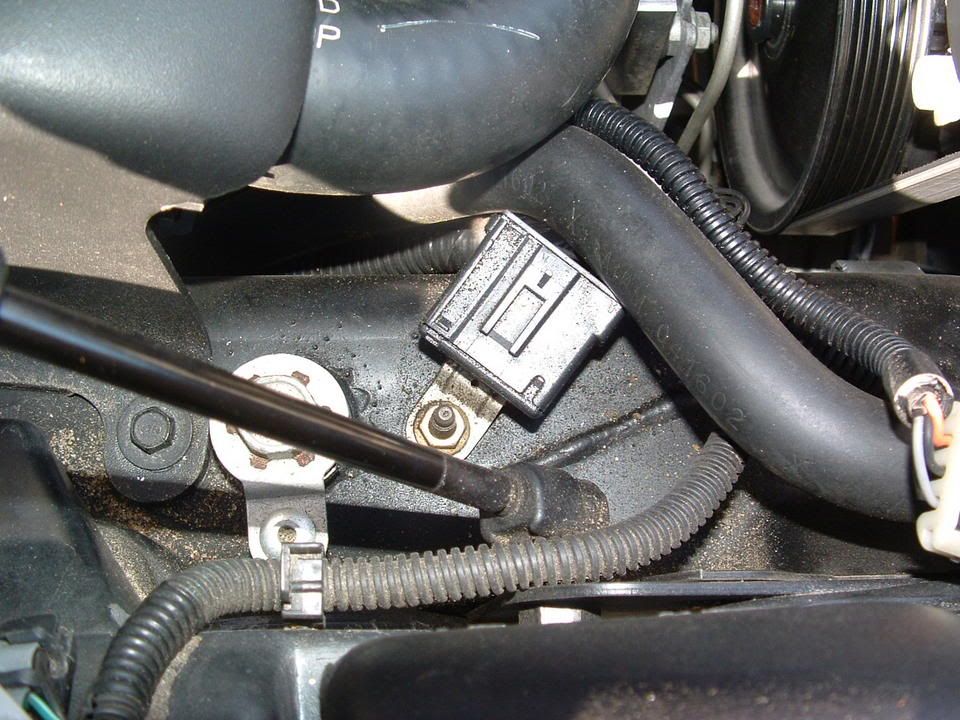
Picture of under hood Chassis Ground connector G-101
Corrosion inside connector! (You ain't seen nothing yet!)
[IMG]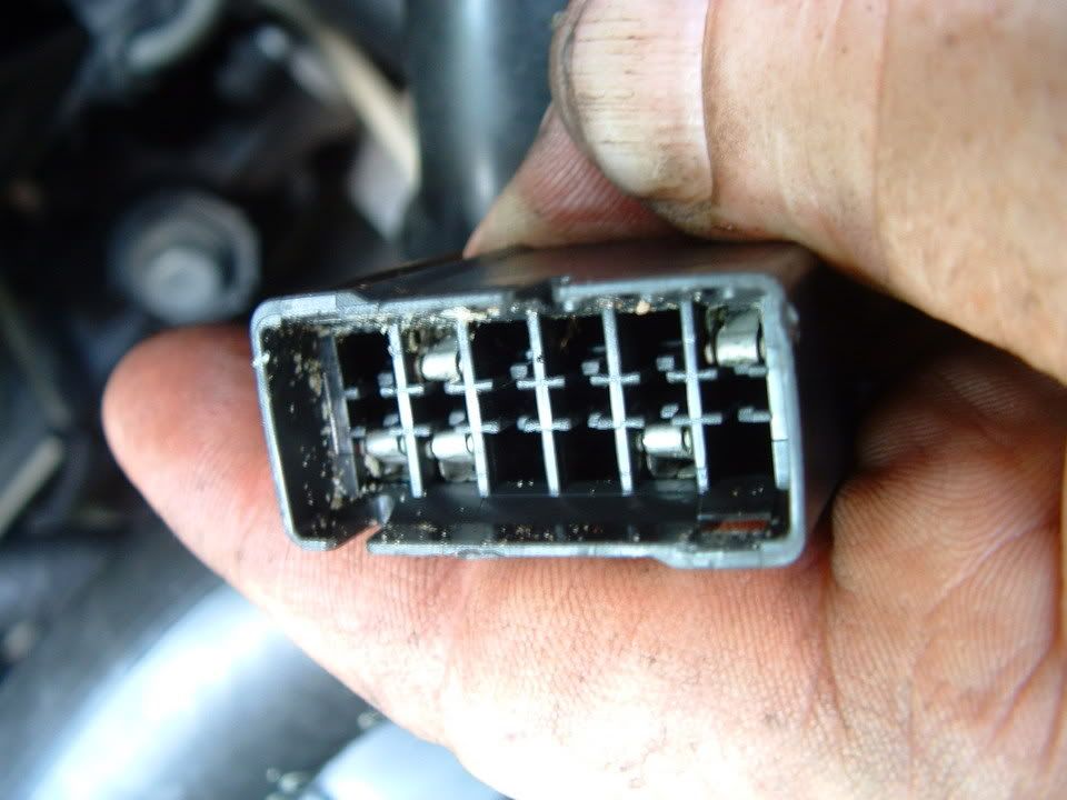 [/IMG]
Next three photos are of the corrosion found on the connector terminals!
[IMG]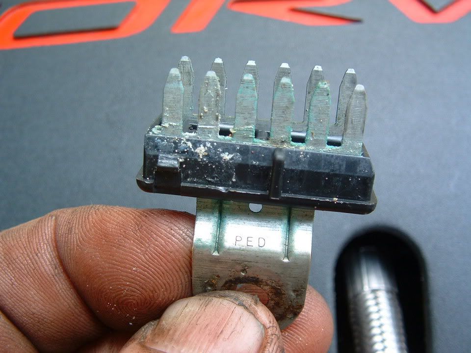 [/IMG] [IMG]
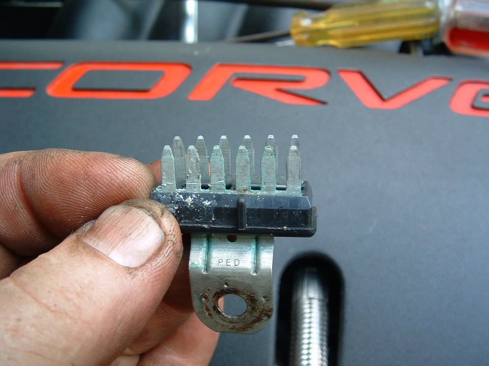 [/IMG] [IMG]
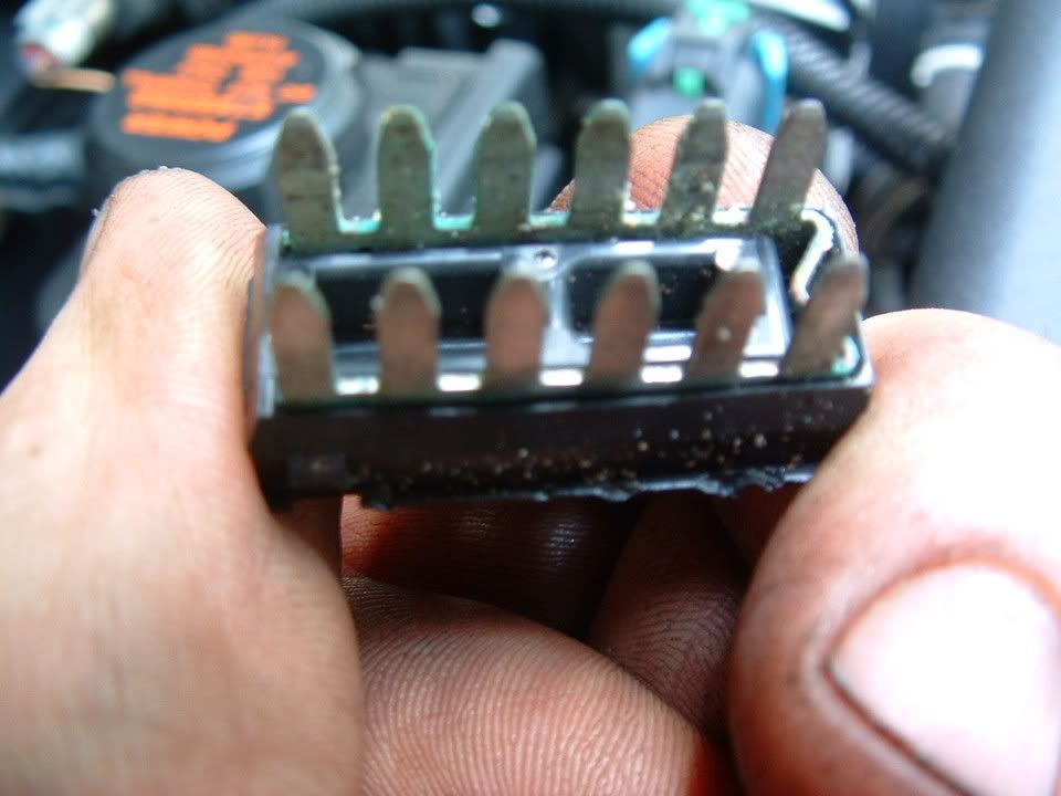 [/IMG]
Self tapping ground screw and star washer. This is what you will need if the ground stud breaks off during removal!
[IMG]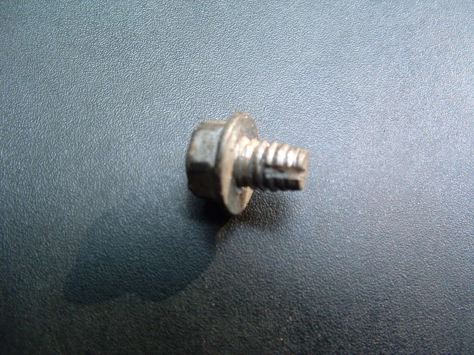 [/IMG] [IMG][IMG]
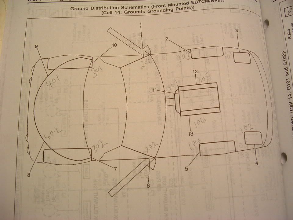
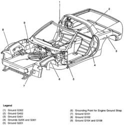
Here are where the chassis ground points are on a C5:

PLEASE let me know if you have any questions.
Bill Curlee
updated 02 March 06
My 98 coupe would get the infamous "REDUCED ENGINE POWER", "TRACTION CONTROL FAILURE" and a host of random failure codes. After many, many hours of troubleshooting, replacing the BCM and TAC module, I solved most of the driveability issues. Still getting the random DTC failure codes, I thought that I may be having ground issues. Back in June I cleaned ALL of the chassis grounds and the car virtually stopped throwing the "RANDOM" DTC failure codes. Just moving the wires in the chassis ground connector was enough to change the indications and make the issues stop happening.
I had a chance to speak with some GM C5 Trouble Desk Engineers when I went to Bowling Green KY in April and they pointed out that MANY of the C5 electrical issues can be directly linked to chassis ground problems. The engineer even went as far as to recommending that I chop off the factory under hood chassis ground connectors and combine all of the wires into a single ground lug. Not wanting to just LOP off the factory connector, I took a chance and disassembled one of the ground plug connectors and to my surprise it was indeed full of corroded connections.
I strongly recommend that any C5 owner that has had or who are having electrical issues, examine and clean the chassis ground connectors. This may save you from needlessly replacing expensive electronics modules. Each ground connector can be disassembled and cleaned in about 20 min.
Just cleaning the metal ground connection between the chassis and the plug is only a band aid solution. Now that I look back, when I cleaned my chassis grounds and initially solved my issues, I believe that when the connector is being removed to clean the connection between chassis and the connector, just the wires being moved inside the plug is what changed the indications and made everything work better.
Disassembly of the chassis ground plug and cleaning the contacts inside the connector is the correct method of solving the issue!
I took some pictures of the under hood chassis ground connector and the corrosion that was in it. I cleaned the two connections on the frame rails and the left one was significantly corroded! Taking it apart and cleaning it is a very straight forward procedure and I believe that if you follow this recommendation, you will be on the way to solving the many of the electrical issues.
Here are some detailed pictures of the ground connector and the corrosion that was found inside it!
Picture of under hood Chassis Ground connector G-101
Corrosion inside connector! (You ain't seen nothing yet!)
[IMG]
[/IMG] Next three photos are of the corrosion found on the connector terminals!
[IMG]
[/IMG] [IMG][/IMG] [IMG][/IMG] Self tapping ground screw and star washer. This is what you will need if the ground stud breaks off during removal!
[IMG]
[/IMG] [IMG][IMG]Here are where the chassis ground points are on a C5:
PLEASE let me know if you have any questions.
Bill Curlee
updated 02 March 06

Heel & Toe

Joined: Nov 2012
Posts: 21
Likes: 4
So, I had the ABS light that would intermittently come on every ignition cycle, probably 90% of the time.
I went ahead and checked my left ground point (a total PITA to get apart) and there was no corrosion whatsoever. I took apart the right side, and there was no visible corrosion, but when I tapped the housing, all this white dust flew out.
I put my car back together, and started her up, and no ABS light. I started the vehicle about 4 times and no ABS light at all. It almost seems too good to be true.
The crazy thing is the car almost seems like it runs a lot better now too. It's probably all in my head though.
Thanks for all the great info, I really appreciate it, it definitely beats removing the EBCM and taking a soldering iron to it.

Cruising
Joined: Jun 2013
Posts: 13
Likes: 0
This might be the best news I've had this year. I'm going through some brand new issues of which we thought were the alternator, battery, etc. I'm getting these 'traction control' and 'active handling' messages. You just made my YEAR!!!! Thank you!!!
Many of you have asked me for help on solving electrical problems and I thought this would be VERY interesting!
My 98 coupe would get the infamous "REDUCED ENGINE POWER", "TRACTION CONTROL FAILURE" and a host of random failure codes. After many, many hours of troubleshooting, replacing the BCM and TAC module, I solved most of the driveability issues. Still getting the random DTC failure codes, I thought that I may be having ground issues. Back in June I cleaned ALL of the chassis grounds and the car virtually stopped throwing the "RANDOM" DTC failure codes. Just moving the wires in the chassis ground connector was enough to change the indications and make the issues stop happening.
I had a chance to speak with some GM C5 Trouble Desk Engineers when I went to Bowling Green KY in April and they pointed out that MANY of the C5 electrical issues can be directly linked to chassis ground problems. The engineer even went as far as to recommending that I chop off the factory under hood chassis ground connectors and combine all of the wires into a single ground lug. Not wanting to just LOP off the factory connector, I took a chance and disassembled one of the ground plug connectors and to my surprise it was indeed full of corroded connections.
I strongly recommend that any C5 owner that has had or who are having electrical issues, examine and clean the chassis ground connectors. This may save you from needlessly replacing expensive electronics modules. Each ground connector can be disassembled and cleaned in about 20 min.
Just cleaning the metal ground connection between the chassis and the plug is only a band aid solution. Now that I look back, when I cleaned my chassis grounds and initially solved my issues, I believe that when the connector is being removed to clean the connection between chassis and the connector, just the wires being moved inside the plug is what changed the indications and made everything work better.
Disassembly of the chassis ground plug and cleaning the contacts inside the connector is the correct method of solving the issue!
I took some pictures of the under hood chassis ground connector and the corrosion that was in it. I cleaned the two connections on the frame rails and the left one was significantly corroded! Taking it apart and cleaning it is a very straight forward procedure and I believe that if you follow this recommendation, you will be on the way to solving the many of the electrical issues.
Here are some detailed pictures of the ground connector and the corrosion that was found inside it!
Picture of under hood Chassis Ground connector G-101
Corrosion inside connector! (You ain't seen nothing yet!)
[IMG][/IMG]
Next three photos are of the corrosion found on the connector terminals!
[IMG][/IMG] [IMG][/IMG] [IMG][/IMG]
Self tapping ground screw and star washer. This is what you will need if the ground stud breaks off during removal!
[IMG][/IMG] [IMG][IMG]
Here are where the chassis ground points are on a C5:
PLEASE let me know if you have any questions.
Bill Curlee
updated 02 March 06
My 98 coupe would get the infamous "REDUCED ENGINE POWER", "TRACTION CONTROL FAILURE" and a host of random failure codes. After many, many hours of troubleshooting, replacing the BCM and TAC module, I solved most of the driveability issues. Still getting the random DTC failure codes, I thought that I may be having ground issues. Back in June I cleaned ALL of the chassis grounds and the car virtually stopped throwing the "RANDOM" DTC failure codes. Just moving the wires in the chassis ground connector was enough to change the indications and make the issues stop happening.
I had a chance to speak with some GM C5 Trouble Desk Engineers when I went to Bowling Green KY in April and they pointed out that MANY of the C5 electrical issues can be directly linked to chassis ground problems. The engineer even went as far as to recommending that I chop off the factory under hood chassis ground connectors and combine all of the wires into a single ground lug. Not wanting to just LOP off the factory connector, I took a chance and disassembled one of the ground plug connectors and to my surprise it was indeed full of corroded connections.
I strongly recommend that any C5 owner that has had or who are having electrical issues, examine and clean the chassis ground connectors. This may save you from needlessly replacing expensive electronics modules. Each ground connector can be disassembled and cleaned in about 20 min.
Just cleaning the metal ground connection between the chassis and the plug is only a band aid solution. Now that I look back, when I cleaned my chassis grounds and initially solved my issues, I believe that when the connector is being removed to clean the connection between chassis and the connector, just the wires being moved inside the plug is what changed the indications and made everything work better.
Disassembly of the chassis ground plug and cleaning the contacts inside the connector is the correct method of solving the issue!
I took some pictures of the under hood chassis ground connector and the corrosion that was in it. I cleaned the two connections on the frame rails and the left one was significantly corroded! Taking it apart and cleaning it is a very straight forward procedure and I believe that if you follow this recommendation, you will be on the way to solving the many of the electrical issues.
Here are some detailed pictures of the ground connector and the corrosion that was found inside it!
Picture of under hood Chassis Ground connector G-101
Corrosion inside connector! (You ain't seen nothing yet!)
[IMG]
[/IMG] Next three photos are of the corrosion found on the connector terminals!
[IMG]
[/IMG] [IMG][/IMG] [IMG][/IMG] Self tapping ground screw and star washer. This is what you will need if the ground stud breaks off during removal!
[IMG]
[/IMG] [IMG][IMG]Here are where the chassis ground points are on a C5:
PLEASE let me know if you have any questions.
Bill Curlee
updated 02 March 06
Safety Car

Joined: Jun 2014
Posts: 4,637
Likes: 0
From: WDE
St. Jude Donor '14-'15
Wish someone knew which grounds went to which electronics.. I'm in the middle of fixing my abs and traction control system and I've already tried the 2 grounds by both headlights..

2nd Gear
Joined: Jun 2014
Posts: 2
Likes: 0
I have a 97 c5 headlights will not come on doors not go up. Only have high beams if you hold the light sw back. Disconnected the grey connectors and read voltage in fuse box, seems OK. When I plug the grey headlight connectors together the voltage drops way off or completely goes away. Pull fuse 10 and the doors go up. Jump voltage to the lights directly and the work. Help
Melting Slicks

Joined: Sep 2012
Posts: 2,308
Likes: 159
From: LaGrange Park, IL IL
St. Jude Donor '13, '15
I had originally posted this in the C5 General forum and received a link to this post. Was astonished to see it 82 pages long and still alive since 2004. I think my problem may be in G104, but posting here to get some more opinions before I start to tackle this.
I have clear corners with LED switchbacks and HID fogs both of which have been installed in the car for over a year now and no issues. I have a resistor added as well to prevent hyperflash.
Noticed when I left my house this evening that my passenger side DRL flickered a bit and took about 1-2 seconds longer to eventually light up than the driver side when I pushed the unlock button on my key fob. But it did light up. My fogs lit up as well as part of the unlock feature.
While I was out we had some heavy rains and I was back to my car about 2 hours from the time I left the house. Went back out to the car and pressed the unlock on the key fob and again the DRL flickered. When I got home 5 minutes later the DRL was out. I thought I just blew the switchback, but upon trying other lights, I see the passenger side fog light was not working either???
So in summary: Both headlights work, but only drivers side DRL and drivers side fog work. Passenger side DRL and passenger side fog, both out. Passenger turn signal does not work (front only/rear is working as normal). Nothing else in the interior seemed out of place. No codes, battery tested good.

Thread Starter
Tech Contributor


Joined: Dec 1999
Posts: 32,910
Likes: 2,402
From: Anthony TX
CI 6,7,8,9,11 Vet
St. Jude Donor '08
There is a ground block or what is refered to as a splice pack (SP) under the front facia. Its secured to a wire harness that runs across the facia. That SP contains many of the ground wires for all the front end lighting. Start there. Check the grounds at G-101 & G102.
SP

SP
Corvette Stories
The Best of Corvette for Corvette Enthusiasts

Top 10 Most Expensive Corvettes Ever Sold on Bring A Trailer
Brett Foote
10 Things Every Corvette Owner Needs (2026 Edition)
Michael S. Palmer
8 Most "Only Corvette Owners Understand" Quirks and Problems
Pouria Savadkouei
10 Reasons the C6 Z06 is Still A Performance Benchmark After 20 Years
Joe Kucinski
How Much Horsepower Every Corvette Engine "LOST" in 1972
Joe Kucinski
Top 10 DOs and DON'Ts for Protecting Your Convertible Top!
Michael S. Palmer
Top 10 Most Explosive Corvettes Ever Made: Power-to-Weight Ratio Ranked!
Joe Kucinski
150 hp to 1,250 hp: Every Corvette Generation Compared by the Specs That Matter
Joe Kucinski
8 Coolest Corvette Pace Cars (and Replicas) of All Time
Verdad GallardoMelting Slicks
Joined: Sep 2012
Posts: 2,308
Likes: 159
From: LaGrange Park, IL IL
St. Jude Donor '13, '15
Didn't think to ask this earlier, but what exactly should I be looking for or checking at that splice block in the front fascia? Do I open it up to look at connectors like the ones on the frame rail, or just loose/frayed wires?
If I jack the car up will this splice block be fairly easy to access, or is it hidden in there?
We had a lot of storms here the last week and unfortunately I got stuck out in some of it. Wonder if some water shorted something down there?
If I jack the car up will this splice block be fairly easy to access, or is it hidden in there?
We had a lot of storms here the last week and unfortunately I got stuck out in some of it. Wonder if some water shorted something down there?
Thread Starter
Tech Contributor
Joined: Dec 1999
Posts: 32,910
Likes: 2,402
From: Anthony TX
CI 6,7,8,9,11 Vet
St. Jude Donor '08
Didn't think to ask this earlier, but what exactly should I be looking for or checking at that splice block in the front fascia? Do I open it up to look at connectors like the ones on the frame rail, or just loose/frayed wires?
If I jack the car up will this splice block be fairly easy to access, or is it hidden in there?
We had a lot of storms here the last week and unfortunately I got stuck out in some of it. Wonder if some water shorted something down there?
If I jack the car up will this splice block be fairly easy to access, or is it hidden in there?
We had a lot of storms here the last week and unfortunately I got stuck out in some of it. Wonder if some water shorted something down there?
Pop the white end cap off the SP and extract the ground buss from the plug.
BC
Melting Slicks
Joined: Sep 2012
Posts: 2,308
Likes: 159
From: LaGrange Park, IL IL
St. Jude Donor '13, '15
I'm deleting my earlier posts and consolidating and summarizing in this one just to clean up the thread.
Checked the G104 and G102 connectors and all is clean. G101 and the Splice Block in the front fascia were good too. G104 was also good. I swapped fog light bulbs side to side and proved the bulb in the fog at least is good. I checked all the splices and wiring for the DRLs and fogs and everything was solid. Gave some tugs and wiggle of the wires to see if the light would go on intermittently and nothing. I also checked the fuse panel underhood for the common fuses associated with the Fogs and DRLs and they checked out good. Not sure how to check relays so I just swapped one for another and didn't see any change in the end result, so I'm assuming that means the relay is good.
Went back to the G102 again and noticed when I was putting the plug back into the connector about half way I was getting a clicking noise somewhere in the headlights area. Put my hand on the headlamp motors and could feel the pulse there...seemed like both sides. Pushing the plug into the connector all the way it continued to click up to the point that I that I touched the connector back to the frame ground. This happened the first time I checked out G102 also. Troubleshooting after that caused the headlamp buckets acting strange and not closing all the way. Sometimes about 60% and other times about 90%, eventually I get them to close all the way. They also opened with just the parking lights once.
Finally I swapped the DRL switchback bulbs side to side since I was down there anyway after getting to the splice pack. I found the passenger light bulb bad...not wanting to go another day without a turn signal, I put the original halogen bulbs back in the housings on both sides and have at least fixed that issue. Not sure how long this will last as I'm concerned something is still wrong and caused the issue in the first place. Passenger side fog lamp is still not working, but I don't use them much so I have some time to figure out that issue. My next attempt is to put the original bulb back in that housing and bypass the HID ballast. I also have extra resistors, so I may try that too. Ran out of time today...and energy.

3rd Gear
Joined: Jun 2014
Posts: 3
Likes: 0
I am a fairly new corvette owner and have found this forum very helpful for DIY repairs. I just repaired my headlight only to find out that my A/C blower motor quit working without any kind of warning. I did check the fuses and they are fine. After reading about the grounding issue, do you think it is possible that this could be my problem as well. The car is a 2002 with only 8,000 miles on it. I guess the grounding points could as easily corrode sitting in a garage as being out in the weather?

Pro


Joined: Jul 2007
Posts: 587
Likes: 18
From: Tampa FL
I am a fairly new corvette owner and have found this forum very helpful for DIY repairs. I just repaired my headlight only to find out that my A/C blower motor quit working without any kind of warning. I did check the fuses and they are fine. After reading about the grounding issue, do you think it is possible that this could be my problem as well. The car is a 2002 with only 8,000 miles on it. I guess the grounding points could as easily corrode sitting in a garage as being out in the weather?

Intermediate
Joined: Jan 2013
Posts: 35
Likes: 0
From: San Tan Arizona
I just upgraded my 2004 LS1 engine with Port polished 243 heads, Lunati cam, long tube exhaust, Air Raid CAI, Stage 3 Transmission, and some small other items. Also had Professionally tuned/Dyno by Nic D (Excellent professional guy). I also had my water pump, valve covers, and alternator bracket powder coated. Here is the issue. I have to rev the RPM's about 4000 before the Alternator starts to charge around 13.3v (Which I think should be more than that). Also if i turn on any accessories it will read a lower voltage.Before I rev motor it is about 11.8v. I replace alternator and have new Optima Red top battery. I checked all ground locations they are all tight. Also these readings are from my DVM, not just from the display in car. I did research on internet and maybe starter connections, but I check all connections and they are tight. I do get error saying sytem fault voltage Any ideas would be helpful,
Thank you in advance,
Jimmy
Thank you in advance,
Jimmy
Thread Starter
Tech Contributor
Joined: Dec 1999
Posts: 32,910
Likes: 2,402
From: Anthony TX
CI 6,7,8,9,11 Vet
St. Jude Donor '08
I just upgraded my 2004 LS1 engine with Port polished 243 heads, Lunati cam, long tube exhaust, Air Raid CAI, Stage 3 Transmission, and some small other items. Also had Professionally tuned/Dyno by Nic D (Excellent professional guy). I also had my water pump, valve covers, and alternator bracket powder coated. Here is the issue. I have to rev the RPM's about 4000 before the Alternator starts to charge around 13.3v (Which I think should be more than that). Also if i turn on any accessories it will read a lower voltage.Before I rev motor it is about 11.8v. I replace alternator and have new Optima Red top battery. I checked all ground locations they are all tight. Also these readings are from my DVM, not just from the display in car. I did research on internet and maybe starter connections, but I check all connections and they are tight. I do get error saying sytem fault voltage Any ideas would be helpful,
Thank you in advance,
Jimmy
Thank you in advance,
Jimmy
The alternator CASE needs to be grounded to the engine. Measure the case (bare metal somewhere) to engine ground and then battery Neg. with an OHM Meter.
If you have HIGH RESISTANCE, that is an issue. I grounded my Alt Case to Chassis ground G-101 using one of the Alternator case bolts and a 10 gage stranded wire to chassis ground..
Also attach a temporary jumper wire from the battery positive terminal to the BATT terminal on the back of the alternator.
See if the battery charging voltage increases. If it does, you have a poor connection between the alternator BATT terminal and the battery.
Ground the alternator case first and see if it makes a difference.
Bill
Intermediate
Joined: Jan 2013
Posts: 35
Likes: 0
From: San Tan Arizona
[QUOTE=Bill Curlee;1587221889]Jimmy
The alternator CASE needs to be grounded to the engine. Measure the case (bare metal somewhere) to engine ground and then battery Neg. with an OHM Meter.
If you have HIGH RESISTANCE, that is an issue. I grounded my Alt Case to Chassis ground G-101 using one of the Alternator case bolts and a 10 gage stranded wire to chassis ground..
Also attach a temporary jumper wire from the battery positive terminal to the BATT terminal on the back of the alternator.
See if the battery charging voltage increases. If it does, you have a poor connection between the alternator BATT terminal and the battery.
Ground the alternator case first and see if it makes a difference.
I checked Alt to G101 and read .2ohms. Then read to G103 and read .2ohms. Then Battery GND post to Terminal was .2ohms. Then Neg battery post to G104 read .2ohms. With car off battery reads 12.42 Volts. Also read Positive battery post to Alt power terminal read .2ohms. I start car battery read 12Vdc. Alternator power to G101 I read 11.99Vdc. With car running I read 10ohms from battery to G104 or Aluminum head same reading. I also read 2ohms on Alt to G101. When i rev car up to 4500 rpm car reads at battery 13.2Vdc. When i did check to see if all the wires were tight on Starter they were, but when i loosen the main Solenoid wires the post is loose, but it tightens up when i put cables back on and the nut. Also I don't think it would be fuse-able links, because wouldn't the wires always read open circuit. Not sure what to do next. I probably lost you on the first couple of sentences,lol.. One more thing I did run wire for the heck of it to ALT to G101 with no difference and a wire from Neg battery post to G104. No help,, I left all wires still connected when I did this.
Thanks,
Jimmy
The alternator CASE needs to be grounded to the engine. Measure the case (bare metal somewhere) to engine ground and then battery Neg. with an OHM Meter.
If you have HIGH RESISTANCE, that is an issue. I grounded my Alt Case to Chassis ground G-101 using one of the Alternator case bolts and a 10 gage stranded wire to chassis ground..
Also attach a temporary jumper wire from the battery positive terminal to the BATT terminal on the back of the alternator.
See if the battery charging voltage increases. If it does, you have a poor connection between the alternator BATT terminal and the battery.
Ground the alternator case first and see if it makes a difference.
I checked Alt to G101 and read .2ohms. Then read to G103 and read .2ohms. Then Battery GND post to Terminal was .2ohms. Then Neg battery post to G104 read .2ohms. With car off battery reads 12.42 Volts. Also read Positive battery post to Alt power terminal read .2ohms. I start car battery read 12Vdc. Alternator power to G101 I read 11.99Vdc. With car running I read 10ohms from battery to G104 or Aluminum head same reading. I also read 2ohms on Alt to G101. When i rev car up to 4500 rpm car reads at battery 13.2Vdc. When i did check to see if all the wires were tight on Starter they were, but when i loosen the main Solenoid wires the post is loose, but it tightens up when i put cables back on and the nut. Also I don't think it would be fuse-able links, because wouldn't the wires always read open circuit. Not sure what to do next. I probably lost you on the first couple of sentences,lol.. One more thing I did run wire for the heck of it to ALT to G101 with no difference and a wire from Neg battery post to G104. No help,, I left all wires still connected when I did this.
Thanks,
Jimmy
Thread Starter
Tech Contributor
Joined: Dec 1999
Posts: 32,910
Likes: 2,402
From: Anthony TX
CI 6,7,8,9,11 Vet
St. Jude Donor '08
[QUOTE=xtremeironworks;1587229104]
Jimmy
All understood! The LOOSE terminal on the starter solenoid
bothers me.
IF,,,,,,, you run a jumper wire from the POS Batt terminal to the BATT terminal on the back of the alternator, does the battery charging voltage INCREASE?
You can read battery voltage to ground on ANY of the fused links to prove that they are GOOD.
Bill
Jimmy
The alternator CASE needs to be grounded to the engine. Measure the case (bare metal somewhere) to engine ground and then battery Neg. with an OHM Meter.
If you have HIGH RESISTANCE, that is an issue. I grounded my Alt Case to Chassis ground G-101 using one of the Alternator case bolts and a 10 gage stranded wire to chassis ground..
Also attach a temporary jumper wire from the battery positive terminal to the BATT terminal on the back of the alternator.
See if the battery charging voltage increases. If it does, you have a poor connection between the alternator BATT terminal and the battery.
Ground the alternator case first and see if it makes a difference.
I checked Alt to G101 and read .2ohms. Then read to G103 and read .2ohms. Then Battery GND post to Terminal was .2ohms. Then Neg battery post to G104 read .2ohms. With car off battery reads 12.42 Volts. Also read Positive battery post to Alt power terminal read .2ohms. I start car battery read 12Vdc. Alternator power to G101 I read 11.99Vdc. With car running I read 10ohms from battery to G104 or Aluminum head same reading. I also read 2ohms on Alt to G101. When i rev car up to 4500 rpm car reads at battery 13.2Vdc. When i did check to see if all the wires were tight on Starter they were, but when i loosen the main Solenoid wires the post is loose, but it tightens up when i put cables back on and the nut. Also I don't think it would be fuse-able links, because wouldn't the wires always read open circuit. Not sure what to do next. I probably lost you on the first couple of sentences,lol.. One more thing I did run wire for the heck of it to ALT to G101 with no difference and a wire from Neg battery post to G104. No help,, I left all wires still connected when I did this.
Thanks,
Jimmy
All understood!
The LOOSE terminal on the starter solenoid bothers me.
IF,,,,,,, you run a jumper wire from the POS Batt terminal to the BATT terminal on the back of the alternator, does the battery charging voltage INCREASE?
You can read battery voltage to ground on ANY of the fused links to prove that they are GOOD.
Bill
Intermediate
Joined: Jan 2013
Posts: 35
Likes: 0
From: San Tan Arizona
I ran a 1/0 cable from Alt to Battery post and when I rev up it will not charge. it only stays at 11.99 volts. This seems so weird to me because if I installed a wire straight from battery to alternator. and I ran an extra wire to from alt case to GND, just to make sure its grounded really good, wouldn't that bypass all the wiring from the starter to eliminate the starter. Also before the direct cable from Alt to batt it would charge after reving motor RPM;s What about the three wires going into the starter, they are in a connector. I unplugged the batter checked the Computer plug ins and they all look good, and there is no acid leak from battery.
I really appreciate your time and patience Bill, helping me out.
Jimmy
I really appreciate your time and patience Bill, helping me out.
Jimmy

Burning Brakes


Joined: Apr 2004
Posts: 786
Likes: 46
From: Tucson, AZ
Bill, your help on electrical issues is awesome. I have started to read through this thread, but wanted to post my issue in hopes of a shortcut.
Today I changed the driver�s window regulator and accelerator pedal by removing the pedal unit. Now my door locks and passenger window will not work (but unlock works and lock works by key fob). After about 10min of driving the car goes crazy with no working gauges, radio, AC, various codes� but still gets me home. It happened in the past and I cleaned both my front ground connectors without any issues until today. Seems it has to be something I touched today.
I put some liquid and regular electrical tape on the drivers side exposed serial bus wire between the door and frame. I did kinda bang up the brittle drivers electrical panel trying to get it out.
Any help would be greatly appreciated!
Thread Starter
Tech Contributor
Joined: Dec 1999
Posts: 32,910
Likes: 2,402
From: Anthony TX
CI 6,7,8,9,11 Vet
St. Jude Donor '08
I ran a 1/0 cable from Alt to Battery post and when I rev up it will not charge. it only stays at 11.99 volts. This seems so weird to me because if I installed a wire straight from battery to alternator. and I ran an extra wire to from alt case to GND, just to make sure its grounded really good, wouldn't that bypass all the wiring from the starter to eliminate the starter. Also before the direct cable from Alt to batt it would charge after reving motor RPM;s What about the three wires going into the starter, they are in a connector. I unplugged the batter checked the Computer plug ins and they all look good, and there is no acid leak from battery.
I really appreciate your time and patience Bill, helping me out.
Jimmy
I really appreciate your time and patience Bill, helping me out.
Jimmy
Here is an Alternator Schematic. Start bt checking voltages on the small connector on the alt. Where it goes to the starter or battery, you should see full battery voltage to ground. You also nee to see the GEN TURN ON signal from the PCM.
If you have all that, it should work.

Joshboody
Sounds like you have a Serial Data Buss issue. Most likely causes by a POOR electrical contact between a male and female pin in the Door wiring harness inside the accordion tube.
Read and post your DTCs using the DIC Clear the DTCs and see what comes back.
Disconnect the STAR BUSS for the LDCM, RDCM and SCM. Its the thin electrical connector with four to the left of the BCM It will have FOUR WIRES! Pop the top off of it and remove the buss bar. See if the issue goes away.


You will have NO COMMS in the DIC when you remove the buss bar from the four wire connector.
Bill
Last edited by Bill Curlee; Oct 10, 2014 at 11:51 PM.