


service charging system message
Thread Starter
Instructor


Joined: Dec 2004
Posts: 186
Likes: 0
From: la ca
car starts and then sometimes doesnt start....I'll take it for a drive and when I return, I'll turn it off then on and I get a "SERVICE CHARGING SYSTEM" message and the battery will start dying 14v to 12v down to 5-6v.
I also took my Throttle Body off the car(to wipe it down) and when I reinstalled it, the car now idles HIGH! sometimes the car is driving and the idle stays high. Is the car trying to relearn the part? I've had a TPS error code P0121 for about a year where the check engine light comes on and off....lately more on than off.
WTF is going on with this $50k POS?

Tech Contributor


Joined: Dec 1999
Posts: 32,910
Likes: 2,402
From: Anthony TX
CI 6,7,8,9,11 Vet
St. Jude Donor '08
car starts and then sometimes doesnt start....I'll take it for a drive and when I return, I'll turn it off then on and I get a "SERVICE CHARGING SYSTEM" message and the battery will start dying 14v to 12v down to 5-6v.
I also took my Throttle Body off the car(to wipe it down) and when I reinstalled it, the car now idles HIGH! sometimes the car is driving and the idle stays high. Is the car trying to relearn the part? I've had a TPS error code P0121 for about a year where the check engine light comes on and off....lately more on than off.
WTF is going on with this $50k POS?
I also took my Throttle Body off the car(to wipe it down) and when I reinstalled it, the car now idles HIGH! sometimes the car is driving and the idle stays high. Is the car trying to relearn the part? I've had a TPS error code P0121 for about a year where the check engine light comes on and off....lately more on than off.
WTF is going on with this $50k POS?
The Throttle Position switch issue may be a poor connection at the Connector or a bad TB:
DTC P0121
Circuit Description
The throttle body assembly contains 2 throttle position (TP) sensors. The TP sensors are mounted to the throttle body assembly and are not serviceable. The TP sensors provide a signal voltage that changes relative to throttle blade angle. The engine control module (ECM) supplies the TP sensors with a common 5-volt reference circuit, a common low reference circuit, and 2 independent signal circuits.
The TP sensors have opposite functionality . TP sensor 1 signal voltage decreases from above 4 volts at idle to below 1 volt at wide open throttle (WOT). TP sensor 2 signal voltage increases from below 1 volt at idle to above 4 volts at WOT.
The ECM compares the signal of the TP sensor 1 and TP sensor 2 through the entire range. If the ECM detects a predetermined difference between sensor 1 and sensor 2, or a predetermined difference from the predicted range, this DTC sets.
DTC Descriptor
This diagnostic procedure supports the following DTC:
DTC P0121 Throttle Position (TP) Sensor 1 Performance
Conditions for Running the DTC
• DTCs P0102, P0103, P0107, P0108, P0112, P0113, P0116, P0117, P0118, P0128, P0315, P0335, P0336 are not set.
• The engine speed is more than 450 RPM.
• The ignition 1 voltage is more than 5.23 volts.
• DTC P0121 runs continuously once the above conditions are met.
Conditions for Setting the DTC
The predicted air flow and the predicted MAP combined are outside a calibrated range for more than 3 seconds.
Action Taken When the DTC Sets
The control module illuminates the malfunction indicator lamp (MIL) on the second consecutive ignition cycle that the diagnostic runs and fails.
The control module records the operating conditions at the time the diagnostic fails. The first time the diagnostic fails, the control module stores this information in the Failure Records. If the diagnostic reports a failure on the second consecutive ignition cycle, the control module records the operating conditions at the time of the failure. The control module writes the operating conditions to the Freeze Frame and updates the Failure Records.
Conditions for Clearing the MIL/DTC
The control module turns OFF the malfunction indicator lamp (MIL) after 3 consecutive ignition cycles that the diagnostic runs and does not fail.
A current DTC, Last Test Failed, clears when the diagnostic runs and passes.
A history DTC clears after 40 consecutive warm-up cycles, if no failures are reported by this or any other emission related diagnostic.
Clear the MIL and the DTC with a scan tool.
Diagnostic Aids
• A malfunctioning or damaged throttle body may cause this DTC to set.
• Use the J 35616 Connector Test Adapter Kit for any test that requires probing the ECM harness connector or a component harness connector.
• If there is a condition with the TP sensors, the ECM defaults to reduced power mode for the entire ignition cycle, even if the condition is corrected.
• For an intermittent condition, refer to Intermittent Conditions .
Test Description
The numbers below refer to the step numbers on the diagnostic table.
This step verifies that a condition exists. If there is a condition with a TP sensor circuit, the scan tool will display Disagree.
This step tests for high resistance in the 5-volt reference circuit of the TP sensors. If the DMM does not display more than the specified voltage, there is high resistance in the circuit.
This step tests for high resistance in the low reference circuit of the TP sensor. The ECM must be completely powered down to obtain an accurate resistance reading. It may take up to 30 minutes for the ECM to power down after the ignition key is removed. Removal of the ECM fuse allows the ECM to power down completely.
Step
Action
Values
Yes
No
Schematic Reference: Engine Controls Schematics
Connector End View Reference: Engine Control Module (ECM) Connector End Views or Engine Controls Connector End Views
1
Did you perform the Diagnostic System Check - Vehicle?
--
Go to Step 2
Go to Diagnostic System Check - Vehicle in Vehicle DTC Information
2
Turn ON the ignition, with the engine OFF.
Perform the following tests: • Rapidly depress the accelerator pedal from the rest position to the wide open throttle (WOT) position and release the pedal. Repeat the procedure several times.
• Slowly depress the accelerator pedal to WOT and then slowly return the pedal to closed throttle. Repeat the procedure several times.
Observe the TP Sensor 1 and 2 parameter with a scan tool.
Does the scan tool display Agree?
--
Go to Step 3
Go to Step 5
3
Turn OFF the engine.
Turn ON the ignition, with the engine OFF.
Observe the TP sensor 1 voltage parameter with a scan tool.
Is the voltage within the specified range?
3.4-3.9 V
Go to Step 4
Go to Step 5
4
Observe the Freeze Frame/Failure Records for this DTC.
Turn OFF the ignition for 30 seconds.
Start the engine.
Operate the vehicle within the Conditions for Running the DTC. You may also operate the vehicle within the conditions that you observed from the Freeze Frame/Failure Records.
Did the DTC fail this ignition?
--
Go to Step 5
Go to Diagnostic Aids
5
Turn OFF the ignition.
Notice: Refer to Disengaging Connectors Notice in Cautions and Notices.
Disconnect the throttle body harness connector.
Turn ON the ignition, with the engine OFF.
Important: Use the J 35616-200 Test Lamp Kit for this test. If the J 35616-200 is not available, use a test lamp that measures more than 20 ohms.
Connect a test lamp between the 5-volt reference circuit of the throttle position (TP) sensor and a good ground.
Connect a DMM to the probe of the test lamp and a good ground. Refer to Measuring Voltage Drop in Wiring Systems.
Is the voltage more than the specified value?
4.8 V
Go to Step 6
Go to Step 11
6
Connect a 3-amp fused jumper wire between the 5-volt reference circuit of the TP sensor and the signal 1 circuit of the TP sensor.
Observe the TP sensor 1 voltage parameter with a scan tool.
Is the voltage more than the specified value?
4.8 V
Go to Step 7
Go to Step 9
7
Connect a 3-amp fused jumper wire between the 5-volt reference circuit of the TP sensor and the signal 2 circuit of the TP sensor.
Observe the TP sensor 2 voltage parameter with a scan tool.
Is the voltage more than the specified value?
4.8 V
Go to Step 8
Go to Step 10
8
Turn OFF the ignition.
Remove the ECM fuse from the underhood fuse block.
Notice
Do NOT use a test lamp to test the continuity of the circuit. Damage to the control module may occur due to excessive current draw.
Measure the resistance from the low reference circuit of the TP sensor to a good ground with a DMM.
Is the resistance less than the specified value?
5 ohms
Go to Step 13
Go to Step 12
9
Test the signal 1 circuit of TP sensor for a high resistance or an open. Refer to Circuit Testing and Wiring Repairs in Wiring Systems.
Did you find and correct the condition?
--
Go to Step 17
Go to Step 14
10
Test the signal 2 circuit of TP sensor for a high resistance or an open. Refer to Circuit Testing and Wiring Repairs in Wiring Systems.
Did you find and correct the condition?
--
Go to Step 17
Go to Step 14
11
Important: The 5-volt reference circuits are internally and externally connected at the controller. Other sensors that share the 5-volt reference circuit may also have DTCs set. Disconnecting a sensor on the shared 5-volt reference circuit may isolate a shorted sensor. Review the electrical schematic and diagnose the shared circuits and sensors.
Test the 5-volt reference circuit of the TP sensor and all shared 5-volt reference circuits for a high resistance or an open. Refer to Circuit Testing and Wiring Repairs in Wiring Systems.
Did you find and correct the condition?
--
Go to Step 17
Go to Step 14
12
Test the low reference circuit of the TP sensor for a high resistance or an open. Refer to Circuit Testing and Wiring Repairs in Wiring Systems.
Did you find and correct the condition?
--
Go to Step 17
Go to Step 14
13
Test for shorted terminals and for poor connections at the throttle body. Refer to Testing for Intermittent Conditions and Poor Connections and Connector Repairs in Wiring Systems.
Did you find and correct the condition?
--
Go to Step 17
Go to Step 15
14
Test for shorted terminals and for poor connections at the throttle body and at the engine control module (ECM). Refer to Testing for Intermittent Conditions and Poor Connections and Connector Repairs in Wiring Systems.
Did you find and correct the condition?
--
Go to Step 17
Go to Step 16
15
Replace the throttle body assembly. Refer to Throttle Body Assembly Replacement .
Did you complete the replacement?
--
Go to Step 17
--
16
Replace the ECM. Refer to Control Module References in Computer/Integrating Systems for replacement, setup, and programming.
Did you complete the replacement?
--
Go to Step 17
--
17
Clear the DTCs with a scan tool.
Turn OFF the ignition for 30 seconds.
Start the engine.
Operate the vehicle within the Conditions for Running the DTC. You may also operate the vehicle within the conditions that you observed from the Freeze Frame/Failure Records.
Did the DTC fail this ignition?
--
Go to Step 2
Go to Step 18
18
Observe the Capture Info with a scan tool.
Are there any DTCs that have not been diagnosed?
--
Go to Diagnostic Trouble Code (DTC) List - Vehicle in Vehicle DTC Information
System OK
--------------------------------------------------------------------------------
Document ID# 1481480
2005 Chevrolet Corvette
As for the charging system fault:
Check the battery connections for clean and tight and properly torqued battery terminal connections. Also check the terminals on the starter solenoid for proper tightness. The alternator charges the battery thru the main terminals on the starter solenoid. If that connection is compromised, you will have charge system faults. Also check the BATT connection on the back of the alternator.
CHARGING SCHEMATIC:
Thread Starter
Instructor
Joined: Dec 2004
Posts: 186
Likes: 0
From: la ca
thank you bill curlee!! Great write-up! I will check the battery terminals and all leads at the starter solenoid and also check my throttle body tubing and intake for leaks between the MAF and the TB.
Thread Starter
Instructor
Joined: Dec 2004
Posts: 186
Likes: 0
From: la ca
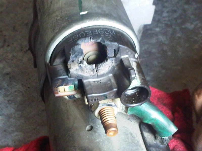
well I check all the wiring and I found the culprit behind my "service charging system" message, it wasn't my alternator or the battery. One of the leads to the starter solenoid was almost completely melted off due to the wire being loose it was heating up pretty bad and thus melted the plastic piece that holds the lead to the starter motor. New starter assembly has been ordered! thank you.
Tech Contributor
Joined: Dec 1999
Posts: 32,910
Likes: 2,402
From: Anthony TX
CI 6,7,8,9,11 Vet
St. Jude Donor '08
You can just replace the solenoid for about $45-$50 That starter is still GOOD! The screws that secure it to the starter are 5/32" and requires a deep well socket to fit in the hole that the one screw lives in.
Bill
Bill
Corvette Stories
The Best of Corvette for Corvette Enthusiasts

Top 10 Most Expensive Corvettes Ever Sold on Bring A Trailer
Brett Foote
10 Things Every Corvette Owner Needs (2026 Edition)
Michael S. Palmer
8 Most "Only Corvette Owners Understand" Quirks and Problems
Pouria Savadkouei
10 Reasons the C6 Z06 is Still A Performance Benchmark After 20 Years
Joe Kucinski
How Much Horsepower Every Corvette Engine "LOST" in 1972
Joe Kucinski
Top 10 DOs and DON'Ts for Protecting Your Convertible Top!
Michael S. Palmer
Top 10 Most Explosive Corvettes Ever Made: Power-to-Weight Ratio Ranked!
Joe Kucinski
150 hp to 1,250 hp: Every Corvette Generation Compared by the Specs That Matter
Joe Kucinski
8 Coolest Corvette Pace Cars (and Replicas) of All Time
Verdad Gallardo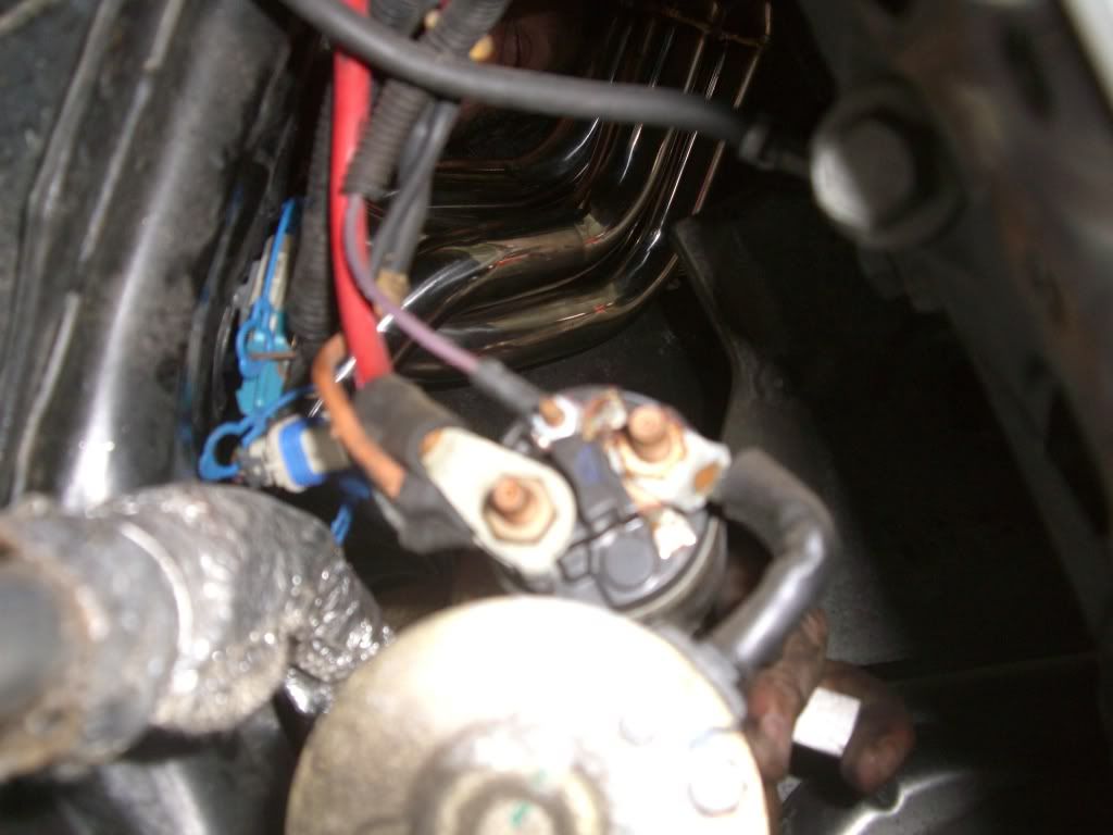
Drifting

Joined: Sep 2009
Posts: 1,995
Likes: 0
From: Somewhere you've probably never heard of in New Mexico
St. Jude Donor '11-'13-'14-'15
I'm having a similar problem with my 07. The dealer replaced the alternator based on some codes they got from the car and a bulletin from GM. It lasted about a week with no problems. After changing the alternator I was getting the SERVICE CHARGING SYSTEM message even more frequently then before and the voltage would show between 11 and 12 but once it showed 16-17v and my wife and I thought we smelled something burning under the hood. No fire or anything but the alternator did smell odd. I saw the picture in this thread of the starter so I put my car on a lift and inspected it and it looked normal.
Does anybody know if the cars stores the codes it posts and for how long? I'm wondering if the dealer can see the one incident of voltage spike. They are getting the car back on Friday.
Does anybody know if the cars stores the codes it posts and for how long? I'm wondering if the dealer can see the one incident of voltage spike. They are getting the car back on Friday.
Tech Contributor
Joined: Dec 2006
Posts: 10,962
Likes: 29
From: Van Buren Arkansas
Wounded Warrior Escort '11
I'm having a similar problem with my 07. The dealer replaced the alternator based on some codes they got from the car and a bulletin from GM. It lasted about a week with no problems. After changing the alternator I was getting the SERVICE CHARGING SYSTEM message even more frequently then before and the voltage would show between 11 and 12 but once it showed 16-17v and my wife and I thought we smelled something burning under the hood. No fire or anything but the alternator did smell odd. I saw the picture in this thread of the starter so I put my car on a lift and inspected it and it looked normal.
Does anybody know if the cars stores the codes it posts and for how long? I'm wondering if the dealer can see the one incident of voltage spike. They are getting the car back on Friday.
Does anybody know if the cars stores the codes it posts and for how long? I'm wondering if the dealer can see the one incident of voltage spike. They are getting the car back on Friday.
Drifting
Joined: Sep 2009
Posts: 1,995
Likes: 0
From: Somewhere you've probably never heard of in New Mexico
St. Jude Donor '11-'13-'14-'15
This morning I started the car and the voltage was 11.5 and the SERVICE CHARGING SYSTEM message came on of course. This time the voltage did not recover to normal and had dropped to 10.9 by the time I got to work. I called the dealer about getting it in today and they said bring it in. I tried to conserve the battery by turning off the headlights, heater fan, radio, and HUD. By the time I got to the dealer the voltage dropped to 8 or less accompanied by many error messages, SHOCKS INOPERATIVE, SERVICE ABS SYSTEM, SERVICE ACTIVE HANDLING, BATTERY VOLTAGE LOW, MAXIMUM SPEED 80 MPH, and the best one, SERVICE VEHICLE SOON. DUH!!!!! When I arrived the car would not turn off with the switch. I kept pushing it then it stopped. I guess I just made it. Whew. Now I'm waiting to hear what they think it is now.
Before I took it in, a friend suggested starting the car and disconnecting the battery to see if the engine dies to indicate the alternator is bad. I did and it died. I told the service guy this and he said it doesn't work that way anymore with all the electronics. They are keeping it overnight. Hopefully they can fix it tomorrow.
Before I took it in, a friend suggested starting the car and disconnecting the battery to see if the engine dies to indicate the alternator is bad. I did and it died. I told the service guy this and he said it doesn't work that way anymore with all the electronics. They are keeping it overnight. Hopefully they can fix it tomorrow.
Tech Contributor
Joined: Dec 1999
Posts: 32,910
Likes: 2,402
From: Anthony TX
CI 6,7,8,9,11 Vet
St. Jude Donor '08
I can not believe that you caved in and took it to the STEALERSHIPS.
I see an easy $$$800.+ hemorrhaging out of your wallet.
I hope that they fix the correct issue the FIRST time.
Oh,,, NEVER disconnect the alternator while the engine is running. I can and will damage the ECM/BCM/IPC and other modules.
BC
I see an easy $$$800.+ hemorrhaging out of your wallet.
I hope that they fix the correct issue the FIRST time.
Oh,,, NEVER disconnect the alternator while the engine is running. I can and will damage the ECM/BCM/IPC and other modules.
BC
Drifting
Joined: Sep 2009
Posts: 1,995
Likes: 0
From: Somewhere you've probably never heard of in New Mexico
St. Jude Donor '11-'13-'14-'15
I bought an extended warranty when I bought the car and it has already paid for itself when they replaced the radio/NAV system and alternator two weeks ago to the tune of $2200. Only cost me $100. Best $1400 I've spent.
I hope I didn't break anything with my disconnecting the battery and if so that the warranty covers it. Guess I shouldn't listen to my "friends".
There was a lot going on with the car when I pulled into the dealer.
I hope I didn't break anything with my disconnecting the battery and if so that the warranty covers it. Guess I shouldn't listen to my "friends".
There was a lot going on with the car when I pulled into the dealer.
Last edited by ABQ C6; Jan 20, 2011 at 10:10 PM.
Tech Contributor
Joined: Dec 2006
Posts: 10,962
Likes: 29
From: Van Buren Arkansas
Wounded Warrior Escort '11
The electrical systems on these cars are nothing like the days of old. Back in those days, that was a valid check but certainly not on most all cars these days.
Tech Contributor
Joined: Dec 1999
Posts: 32,910
Likes: 2,402
From: Anthony TX
CI 6,7,8,9,11 Vet
St. Jude Donor '08
I bought an extended warranty when I bought the car and it has already paid for itself when they replaced the radio/NAV system and alternator two weeks ago to the tune of $2200. Only cost me $100. Best $1400 I've spent.
I hope I didn't break anything with my disconnecting the battery and if so that the warranty covers it. Guess I shouldn't listen to my "friends".
There was a lot going on with the car when I pulled into the dealer.
I hope I didn't break anything with my disconnecting the battery and if so that the warranty covers it. Guess I shouldn't listen to my "friends".
There was a lot going on with the car when I pulled into the dealer.
 Please let us know what they say was at fault.
Bill
Last edited by Bill Curlee; Jan 21, 2011 at 08:12 PM.
Drifting
Joined: Sep 2009
Posts: 1,995
Likes: 0
From: Somewhere you've probably never heard of in New Mexico
St. Jude Donor '11-'13-'14-'15
They're telling me it was a faulty alternator, again. They say they have to order from Detroit because there are none available nearby. Should get it on Tuesday.
I'm not surprised because I was getting the SERVICE CHARGING SYSTEM more after they changed the alternator the first time than before they changed it.
I'm not surprised because I was getting the SERVICE CHARGING SYSTEM more after they changed the alternator the first time than before they changed it.
Tech Contributor
Joined: Dec 1999
Posts: 32,910
Likes: 2,402
From: Anthony TX
CI 6,7,8,9,11 Vet
St. Jude Donor '08
They're telling me it was a faulty alternator, again. They say they have to order from Detroit because there are none available nearby. Should get it on Tuesday.
I'm not surprised because I was getting the SERVICE CHARGING SYSTEM more after they changed the alternator the first time than before they changed it.
I'm not surprised because I was getting the SERVICE CHARGING SYSTEM more after they changed the alternator the first time than before they changed it.
 I would LOVE to be the fly on the wall when this replacement doesn't fix the issue.
If you can,,,, REQUEST and SAVE your OLD parts!!!! Remember. When GM Service replaces your parts,, they use NEW GM parts. You should be able to retain your OLD parts and they ARE VALUABLE!
If there yours, request them and save them. Hell, I will pay shipping for it if you don't want it.

Bill
BC