


PSlow's '72 Restomod Project
Team Owner


Joined: Sep 2006
Posts: 31,301
Likes: 4,389
From: Westminster Maryland
Hi PS,
Interesting photos! Serious work going on!
"Was GM really that careless back in 1972 or is it possible that this engine was rebuilt at some point? Basically, was overspray on the valve train common from the factory?"
The valve covers were in place (whether they were steel, aluminum, or chrome plated, when the engines were painted at both Flint and Tonawanda.
Here's a link to a terrific article written by John Hinkley, (JohnZ), that you may find interesting. 5000 engines a day at Flint in up to 100 configurations!
http://www.camaros.org/pdf/flint_engine.pdf
Regards,
Alan
Nice bonding seam showing through. I forget, is this an original paint car?
Last edited by Alan 71; Jan 15, 2018 at 07:35 AM.
Thread Starter
Burning Brakes

Joined: Sep 2017
Posts: 1,219
Likes: 365
From: Tolland CT
Wow ! I wish I had half the time you have to spend on mine !
Your attention to the details is incredible and I haven't had time to see the video on sandblasting yet but I do still plan on it !
I've been looking in since your first post so I'll be looking in every now and again!
Keep up the good work!
Your attention to the details is incredible and I haven't had time to see the video on sandblasting yet but I do still plan on it !
I've been looking in since your first post so I'll be looking in every now and again!
Keep up the good work!
Anyway, thank you so much for the encouragement and for following my build!
I guess that I am blessed to be very mechanically inclined so a lot of this just 'makes sense' to me. I wish that I understood people half as well as I do machines

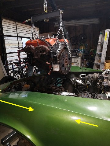
As to the garage, I suppose it is all relative. I find it incredibly cramped. I moved to this house just about a year ago and where I came from had a considerably larger garage. My current work space is very tight and filled with junk. I am not quite sure what I am going to do when I have to lift the body as I will need both bays for the car and it is currently occupied with clutter.
That is an issue for another day however! Thank you again for following my build.
I tough through it because I want to get this done and I need the distraction. I am really hoping that with the ridiculous amount of free time that I have that it will be possible to get this car on the road before next winter. We shall see.
Hi PS, I like the pain formula you are using. The physical part of these restores is tough on the body and the cold doesn't help. The videos are great also as well as your kids helping. Looks like you have things under control. I often call it a day and then go back out to the shop to do a little more. I will keep following your progress.
RVZIO
RVZIO
I agree with you that this is tough on the body and there are a lot of simple things that I took for granted. For instance, try getting up off of a creeper without using your hands.

I think half of the time that I spent removing the engine was me rolling around on the floor like a fish out of water.
I am really hoping that both of my kids will get involved. The youngest really seems to be enjoying himself and I am pleased as punch that we have found something to bond over. My eldest is a little less physical but I will try to coax him out of his shell.
Thank you so much for following my build (I am absolutely following yours)!
Hi PS,
Interesting photos! Serious work going on!
"Was GM really that careless back in 1972 or is it possible that this engine was rebuilt at some point? Basically, was overspray on the valve train common from the factory?"
The valve covers were in place (whether they were steel, aluminum, or chrome plated, when the engines were painted at both Flint and Tonawanda.
Here's a link to a terrific article written by John Hinkley, (JohnZ), that you may find interesting. 5000 engines a day at Flint in up to 100 configurations!
http://www.camaros.org/pdf/flint_engine.pdf
Regards,
Alan
Nice bonding seam showing through. I forget, is this an original paint car?
Interesting photos! Serious work going on!
"Was GM really that careless back in 1972 or is it possible that this engine was rebuilt at some point? Basically, was overspray on the valve train common from the factory?"
The valve covers were in place (whether they were steel, aluminum, or chrome plated, when the engines were painted at both Flint and Tonawanda.
Here's a link to a terrific article written by John Hinkley, (JohnZ), that you may find interesting. 5000 engines a day at Flint in up to 100 configurations!
http://www.camaros.org/pdf/flint_engine.pdf
Regards,
Alan
Nice bonding seam showing through. I forget, is this an original paint car?
As to the paint, as far as I know it is an original paint, no hit body. The paint is VERY rough...lots of checkering throughout so I would not doubt for a second that it was original.
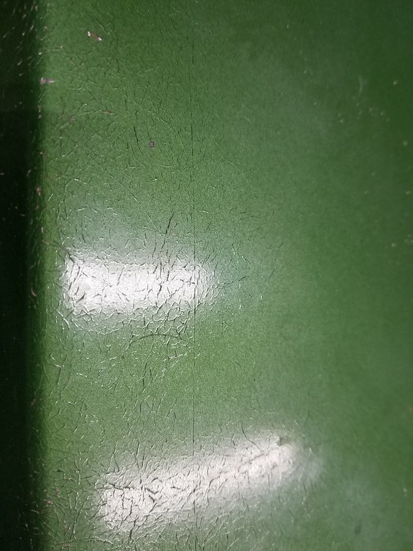
As to the bonding seam, I am clearly not cut out to do an actual restoration to factory specs. The purists and NCRS folks look at that seam and think how cool it looks (and there is nothing wrong with that) but the OCD in me can't wait to fill and block sand that out :-p. I think I will still to resto-mods.
Thread Starter
Burning Brakes
Joined: Sep 2017
Posts: 1,219
Likes: 365
From: Tolland CT
Sorry, I just realized that I never addressed this.
If you are asking which coating system or gun, there are a lot of good quality options out there. I personally use the Spectracoat ES02.
If you are asking what powder do I use: I buy almost all of mine from Prismatic Powders.
Hope that helps but feel free to ask if you have further questions.
If you are asking which coating system or gun, there are a lot of good quality options out there. I personally use the Spectracoat ES02.
If you are asking what powder do I use: I buy almost all of mine from Prismatic Powders.
Hope that helps but feel free to ask if you have further questions.
Thread Starter
Burning Brakes
Joined: Sep 2017
Posts: 1,219
Likes: 365
From: Tolland CT
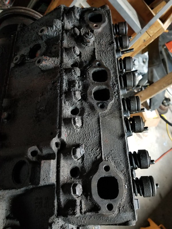
Ugh. Hands hurt and it is freezing out but I am going crazy sitting here so I decided to bundle up and see if I could at least get the exhaust manifolds off of the cylinder heads.
There is 1 bolt on each of the manifolds that appears to literally be welded to the manifold through corrosion. I can turn the manifold in the direction of the bolt slightly and the bolt head moves so I know that it is not frozen into the head but the manifold itself. It is the same on both sides.
I tried for about an hour to free up the left side using PB Blaster, prying, heating it to glowing with a MAP torch, vibration, hitting it with a hammer. I even fashioned up a puller to put pressure on the stud while pulling up on the manifold. Nothing would budge.
Finally I had enough and it was clear that these bolts were not coming out through any conventional means. I really, really hate working this way but sometimes brute force is the answer.
I did a bit of research and it seems that the heads may be of some value but the exhaust manifolds were dime a dozen, my path seemed clear.
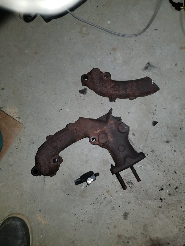
Out came the die grinder, 3" cutoff wheel, a forged chisel, and a 5lb hammer (which incidentally I can barely hold with my hands). Since the bolt was spinning a little when I twisted the manifold I knew that I could simply unthread it if I was able to turn it a full revolution however the ends of the manifold would contact the lower cylinder head bolts, making that impossible.
Some strategic cuts and I made it so that I could spin that bolt around without interference. I am not proud of it, but I did not see any other way.
Cut off one side of the manifold...
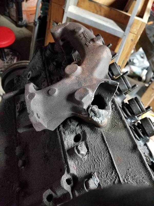
Some further strategic cuts and this is what I was left with...
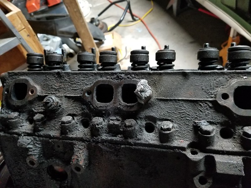
After that, the stud and remaining manifold easily unthreaded from the cylinder head. It wasn't pretty but it worked and without a single mark on the cylinder head.
Bye, bye little exhaust manifold. You will not be missed...
Too cold to continue and I keep dropping tools so it is time to call it a very short day. I will have to tackle the other side (in the exact same condition) tomorrow.
There is 1 bolt on each of the manifolds that appears to literally be welded to the manifold through corrosion. I can turn the manifold in the direction of the bolt slightly and the bolt head moves so I know that it is not frozen into the head but the manifold itself. It is the same on both sides.
I tried for about an hour to free up the left side using PB Blaster, prying, heating it to glowing with a MAP torch, vibration, hitting it with a hammer. I even fashioned up a puller to put pressure on the stud while pulling up on the manifold. Nothing would budge.
Finally I had enough and it was clear that these bolts were not coming out through any conventional means. I really, really hate working this way but sometimes brute force is the answer.
I did a bit of research and it seems that the heads may be of some value but the exhaust manifolds were dime a dozen, my path seemed clear.
Out came the die grinder, 3" cutoff wheel, a forged chisel, and a 5lb hammer (which incidentally I can barely hold with my hands). Since the bolt was spinning a little when I twisted the manifold I knew that I could simply unthread it if I was able to turn it a full revolution however the ends of the manifold would contact the lower cylinder head bolts, making that impossible.
Some strategic cuts and I made it so that I could spin that bolt around without interference. I am not proud of it, but I did not see any other way.
Cut off one side of the manifold...
Some further strategic cuts and this is what I was left with...
After that, the stud and remaining manifold easily unthreaded from the cylinder head. It wasn't pretty but it worked and without a single mark on the cylinder head.
Bye, bye little exhaust manifold. You will not be missed...
Too cold to continue and I keep dropping tools so it is time to call it a very short day. I will have to tackle the other side (in the exact same condition) tomorrow.
Melting Slicks


Joined: Dec 2000
Posts: 3,363
Likes: 303
From: Lansdale 19446 PA
2024 C3 of the Year Finalist- Unmodified
St. Jude Donor '10-'11, '15, '19
PS - two sayings come to mind when I look at the path you took. "A man's gotta do what a man's gotta do" and GET R DONE! You did a great job to keep your progress going forward.
Rest those hand and wrists!!!
Rest those hand and wrists!!!
Last edited by Go Vette Go; Jan 15, 2018 at 04:22 PM.

Safety Car


Joined: Jun 2013
Posts: 4,399
Likes: 793
Ugh. Hands hurt and it is freezing out but I am going crazy sitting here so I decided to bundle up and see if I could at least get the exhaust manifolds off of the cylinder heads.
There is 1 bolt on each of the manifolds that appears to literally be welded to the manifold through corrosion. I can turn the manifold in the direction of the bolt slightly and the bolt head moves so I know that it is not frozen into the head but the manifold itself. It is the same on both sides.
I tried for about an hour to free up the left side using PB Blaster, prying, heating it to glowing with a MAP torch, vibration, hitting it with a hammer. I even fashioned up a puller to put pressure on the stud while pulling up on the manifold. Nothing would budge.
Finally I had enough and it was clear that these bolts were not coming out through any conventional means. I really, really hate working this way but sometimes brute force is the answer.
I did a bit of research and it seems that the heads may be of some value but the exhaust manifolds were dime a dozen, my path seemed clear.
Out came the die grinder, 3" cutoff wheel, a forged chisel, and a 5lb hammer (which incidentally I can barely hold with my hands). Since the bolt was spinning a little when I twisted the manifold I knew that I could simply unthread it if I was able to turn it a full revolution however the ends of the manifold would contact the lower cylinder head bolts, making that impossible.
Some strategic cuts and I made it so that I could spin that bolt around without interference. I am not proud of it, but I did not see any other way.
Cut off one side of the manifold...
Some further strategic cuts and this is what I was left with...
After that, the stud and remaining manifold easily unthreaded from the cylinder head. It wasn't pretty but it worked and without a single mark on the cylinder head.
Bye, bye little exhaust manifold. You will not be missed...
Too cold to continue and I keep dropping tools so it is time to call it a very short day. I will have to tackle the other side (in the exact same condition) tomorrow.
Keep up the nice restoration. Wait until you get to work with nice clean stuff.
RVZIO

Thread Starter
Burning Brakes
Joined: Sep 2017
Posts: 1,219
Likes: 365
From: Tolland CT

Haha, I know what you mean. I have been covered in grease (as you can tell by looking at the engine) for the last few days. I do have a TON of nice new parts waiting for me but I need to get the body off of the frame before I will be able to play with them.
Corvette Stories
The Best of Corvette for Corvette Enthusiasts

Every 2027 Corvette Engine Explained
Joe Kucinski
Designer Imagines A Corvette That Looks More Like a Corvette Than the Corvette
Verdad Gallardo
10 Ugly Corvettes That We Still Kinda Love
Joe Kucinski
Top 10 Most Expensive Corvettes Ever Sold on Bring A Trailer
Brett Foote
10 Things Every Corvette Owner Needs (2026 Edition)
Michael S. Palmer
8 Most "Only Corvette Owners Understand" Quirks and Problems
Pouria Savadkouei
10 Reasons the C6 Z06 is Still A Performance Benchmark After 20 Years
Joe Kucinski
How Much Horsepower Every Corvette Engine "LOST" in 1972
Joe Kucinski
Top 10 DOs and DON'Ts for Protecting Your Convertible Top!
Michael S. Palmer
Thread Starter
Burning Brakes
Joined: Sep 2017
Posts: 1,219
Likes: 365
From: Tolland CT
Well, I couldn't shut my brain off so I had to do some more work but it was too cold in the garage so I restricted myself to my shop.
While I was using the die grinder I noticed that I was getting a lot of water in the air line. I have a desiccant dryer in-line that I just changed yesterday however with the air being so cold and the compressor heating up so much while in use it was causing a ton of water to be in the line. This is bad for my air tools but would be disastrous when it comes time to paint. Obviously the system that I used for drying on my smaller compressor was not up to the task with my new 60 gallon.
Being a giant physics and science geek occasionally has its advantages so I set about to making my own air line dryer system. I can't take complete credit for this as the idea has been passed around for quite some time but it was fun to put it to practical use.
I had a bunch of black iron pipe and various fittings hanging around from past projects so I thought that I would put it to use.
What I am making is a 'drip leg' loop which will be finished by a large filter filled with reusable desiccant pellets.
In the manufacturing facilities that I have built we would usually put a commercial chiller in place...basically a refrigerator that the pipes pass through and forces the air to cool rapidly. Cool air doesn't hold much water, you see.
The problem is that these are expensive and use a lot of power. I am already taxing the 100A service in my garage so I did not want to add to that electrical load so we will let physics work for us.
I whipped up this quick diagram as a blueprint for what I am doing.

It is constructed of 1/2" Black Iron Pipe for the drip legs and the desiccant filter is made from 2" pipe.
The short version is that the hot air coming out of the compressor contains a lot of water in suspension. The air travels through the black iron pipe and transfers a lot of the heat to it through conduction as iron is a great thermal conductor. As the air cools it loses its ability to hold as much water and that is how we get moisture in our lines. Now in this design the water falls out of suspension and is collected at the bottom of the legs which is then removed through the valves at the bottom.
In many cases this would be sufficient to provide dry air but I wanted to be absolutely certain so I added a desiccant filter to the end of the line. This is nothing more than a 2" section of pipe with screens at either end to prevent the desiccant pellets from entering the air line. I added two 45 degree tee's to the design which will make changing out the desiccant easy when the time comes. Simply shut off the air, open the lower tee and the desiccant falls out into a bucket. Replace the cap on the lower tee and then use the upper tee to re-fill the tube with fresh desiccant. Cap it back off, turn on the air and you are good to go.
Total cost would likely be around $100 if you had to buy everything needed but I had a lot of this around the house. The only thing that I needed to buy was the desiccant and a few of the 2" fittings so my out of pocket should be around $40.
Build List:
Qty 3: 1/2" Black Iron Pipe - 6' long
Qty 2: 1/2" x 1/2" x 1/2" Black Iron Tee
Qty 2: 1/2" x 3/8" x 1/2" Black Iron Tee (the 3/8 is what connects to my compressor and air line)
Qty 4: Black Iron 90 Degree Elbow
Qty 3: 1/2" Black Iron Pipe - 2.5" long
Qty 1: 1/2" Black Iron Pipe - 12" long
Qty 1: 2" Black Iron Pipe - 4' long
Qty 2: 2" x 2" x 2" Black Iron 45 Degree Tee
Qty 2: 2" to 1/2" Reducer Cap
Qty 2: 2" End Cap
Qty 2: Some kind of screen. I used some perforated metal that I had lying around.
Qty 4: 1/2" Ball Valve. I actually had hose bibs so I used those.
Qty 1: 5lbs. Silicon Desiccant Beads (see link below). Use the orange stuff as it is manufactured without carcinogens.
You can get the desiccant here: https://www.ebay.com/itm/5-Pounds-of...72.m2749.l2649
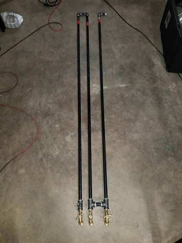
And finally, this is what I have so far. I am waiting on the 2" 45 degree tees then I will be able to fully assemble the unit.
**EDIT**
I should add that this system is expandable. The longer the pipe run that you have, the more cooling takes place and the more water is removed from your air. I chose 6' pipe sections because I have a 9' ceiling height. If you have the ability to run longer pipe, please feel free to do so and your system will be more efficient. Likewise I stopped at 3 loops but there is no reason why you could not continue to add as many loops as you found necessary.
It should also add that in the warmer weather you can increase the efficiency of this design by adding a simple fan blowing on the pipes.
While I was using the die grinder I noticed that I was getting a lot of water in the air line. I have a desiccant dryer in-line that I just changed yesterday however with the air being so cold and the compressor heating up so much while in use it was causing a ton of water to be in the line. This is bad for my air tools but would be disastrous when it comes time to paint. Obviously the system that I used for drying on my smaller compressor was not up to the task with my new 60 gallon.
Being a giant physics and science geek occasionally has its advantages so I set about to making my own air line dryer system. I can't take complete credit for this as the idea has been passed around for quite some time but it was fun to put it to practical use.
I had a bunch of black iron pipe and various fittings hanging around from past projects so I thought that I would put it to use.
What I am making is a 'drip leg' loop which will be finished by a large filter filled with reusable desiccant pellets.
In the manufacturing facilities that I have built we would usually put a commercial chiller in place...basically a refrigerator that the pipes pass through and forces the air to cool rapidly. Cool air doesn't hold much water, you see.
The problem is that these are expensive and use a lot of power. I am already taxing the 100A service in my garage so I did not want to add to that electrical load so we will let physics work for us.
I whipped up this quick diagram as a blueprint for what I am doing.
It is constructed of 1/2" Black Iron Pipe for the drip legs and the desiccant filter is made from 2" pipe.
The short version is that the hot air coming out of the compressor contains a lot of water in suspension. The air travels through the black iron pipe and transfers a lot of the heat to it through conduction as iron is a great thermal conductor. As the air cools it loses its ability to hold as much water and that is how we get moisture in our lines. Now in this design the water falls out of suspension and is collected at the bottom of the legs which is then removed through the valves at the bottom.
In many cases this would be sufficient to provide dry air but I wanted to be absolutely certain so I added a desiccant filter to the end of the line. This is nothing more than a 2" section of pipe with screens at either end to prevent the desiccant pellets from entering the air line. I added two 45 degree tee's to the design which will make changing out the desiccant easy when the time comes. Simply shut off the air, open the lower tee and the desiccant falls out into a bucket. Replace the cap on the lower tee and then use the upper tee to re-fill the tube with fresh desiccant. Cap it back off, turn on the air and you are good to go.
Total cost would likely be around $100 if you had to buy everything needed but I had a lot of this around the house. The only thing that I needed to buy was the desiccant and a few of the 2" fittings so my out of pocket should be around $40.
Build List:
Qty 3: 1/2" Black Iron Pipe - 6' long
Qty 2: 1/2" x 1/2" x 1/2" Black Iron Tee
Qty 2: 1/2" x 3/8" x 1/2" Black Iron Tee (the 3/8 is what connects to my compressor and air line)
Qty 4: Black Iron 90 Degree Elbow
Qty 3: 1/2" Black Iron Pipe - 2.5" long
Qty 1: 1/2" Black Iron Pipe - 12" long
Qty 1: 2" Black Iron Pipe - 4' long
Qty 2: 2" x 2" x 2" Black Iron 45 Degree Tee
Qty 2: 2" to 1/2" Reducer Cap
Qty 2: 2" End Cap
Qty 2: Some kind of screen. I used some perforated metal that I had lying around.
Qty 4: 1/2" Ball Valve. I actually had hose bibs so I used those.
Qty 1: 5lbs. Silicon Desiccant Beads (see link below). Use the orange stuff as it is manufactured without carcinogens.
You can get the desiccant here: https://www.ebay.com/itm/5-Pounds-of...72.m2749.l2649
And finally, this is what I have so far. I am waiting on the 2" 45 degree tees then I will be able to fully assemble the unit.
**EDIT**
I should add that this system is expandable. The longer the pipe run that you have, the more cooling takes place and the more water is removed from your air. I chose 6' pipe sections because I have a 9' ceiling height. If you have the ability to run longer pipe, please feel free to do so and your system will be more efficient. Likewise I stopped at 3 loops but there is no reason why you could not continue to add as many loops as you found necessary.
It should also add that in the warmer weather you can increase the efficiency of this design by adding a simple fan blowing on the pipes.
Last edited by PainfullySlow; Jan 15, 2018 at 09:38 PM.
Pro


Joined: Jun 2005
Posts: 703
Likes: 153
From: Central FL
St. Jude Donor '06 thru'17, '23-'26
I got lucky in that it was a half day for school and my youngest son decided that he wanted to lend a hand. I never was able to bond with my own father over things like this so it is a special treat for me that Aidan chose to come out and help on his own. He actually spent about 2.5 hours helping me (which is about 4 years in adult time) and stayed until I could no longer work. He actually asked if I needed more help tomorrow!

Safety Car
Joined: Jun 2013
Posts: 4,399
Likes: 793
Well, I couldn't shut my brain off so I had to do some more work but it was too cold in the garage so I restricted myself to my shop.
While I was using the die grinder I noticed that I was getting a lot of water in the air line. I have a desiccant dryer in-line that I just changed yesterday however with the air being so cold and the compressor heating up so much while in use it was causing a ton of water to be in the line. This is bad for my air tools but would be disastrous when it comes time to paint. Obviously the system that I used for drying on my smaller compressor was not up to the task with my new 60 gallon.
Being a giant physics and science geek occasionally has its advantages so I set about to making my own air line dryer system. I can't take complete credit for this as the idea has been passed around for quite some time but it was fun to put it to practical use.
I had a bunch of black iron pipe and various fittings hanging around from past projects so I thought that I would put it to use.
What I am making is a 'drip leg' loop which will be finished by a large filter filled with reusable desiccant pellets.
In the manufacturing facilities that I have built we would usually put a commercial chiller in place...basically a refrigerator that the pipes pass through and forces the air to cool rapidly. Cool air doesn't hold much water, you see.
The problem is that these are expensive and use a lot of power. I am already taxing the 100A service in my garage so I did not want to add to that electrical load so we will let physics work for us.
I whipped up this quick diagram as a blueprint for what I am doing.
It is constructed of 1/2" Black Iron Pipe for the drip legs and the desiccant filter is made from 2" pipe.
The short version is that the hot air coming out of the compressor contains a lot of water in suspension. The air travels through the black iron pipe and transfers a lot of the heat to it through conduction as iron is a great thermal conductor. As the air cools it loses its ability to hold as much water and that is how we get moisture in our lines. Now in this design the water falls out of suspension and is collected at the bottom of the legs which is then removed through the valves at the bottom.
In many cases this would be sufficient to provide dry air but I wanted to be absolutely certain so I added a desiccant filter to the end of the line. This is nothing more than a 2" section of pipe with screens at either end to prevent the desiccant pellets from entering the air line. I added two 45 degree tee's to the design which will make changing out the desiccant easy when the time comes. Simply shut off the air, open the lower tee and the desiccant falls out into a bucket. Replace the cap on the lower tee and then use the upper tee to re-fill the tube with fresh desiccant. Cap it back off, turn on the air and you are good to go.
Total cost would likely be around $100 if you had to buy everything needed but I had a lot of this around the house. The only thing that I needed to buy was the desiccant and a few of the 2" fittings so my out of pocket should be around $40.
Build List:
Qty 3: 1/2" Black Iron Pipe - 6' long
Qty 2: 1/2" x 1/2" x 1/2" Black Iron Tee
Qty 2: 1/2" x 3/8" x 1/2" Black Iron Tee (the 3/8 is what connects to my compressor and air line)
Qty 4: Black Iron 90 Degree Elbow
Qty 3: 1/2" Black Iron Pipe - 2.5" long
Qty 1: 1/2" Black Iron Pipe - 12" long
Qty 1: 2" Black Iron Pipe - 4' long
Qty 2: 2" x 2" x 2" Black Iron 45 Degree Tee
Qty 2: 2" to 1/2" Reducer Cap
Qty 2: 2" End Cap
Qty 2: Some kind of screen. I used some perforated metal that I had lying around.
Qty 4: 1/2" Ball Valve. I actually had hose bibs so I used those.
Qty 1: 5lbs. Silicon Desiccant Beads (see link below). Use the orange stuff as it is manufactured without carcinogens.
You can get the desiccant here: https://www.ebay.com/itm/5-Pounds-of...72.m2749.l2649
And finally, this is what I have so far. I am waiting on the 2" 45 degree tees then I will be able to fully assemble the unit.
**EDIT**
I should add that this system is expandable. The longer the pipe run that you have, the more cooling takes place and the more water is removed from your air. I chose 6' pipe sections because I have a 9' ceiling height. If you have the ability to run longer pipe, please feel free to do so and your system will be more efficient. Likewise I stopped at 3 loops but there is no reason why you could not continue to add as many loops as you found necessary.
It should also add that in the warmer weather you can increase the efficiency of this design by adding a simple fan blowing on the pipes.
Drifting


Joined: Mar 2013
Posts: 1,926
Likes: 304
From: Lansing MI
Love the line dryer. This is on my list of things to add to the garage this year. Especially before any paint. I will probably add a couple more long lengths of pipe though. I love the desiccant holder idea.
Thread Starter
Burning Brakes
Joined: Sep 2017
Posts: 1,219
Likes: 365
From: Tolland CT
Believe me, it doesn't happen often so I will take what I can get 
It should work very well. I have read of others having great success with just the drip legs. The Desiccant filter should ensure that I have absolutely dry air to run with.
I just wish that I could have it completed as I went out to the garage today to do some blasting in the 15 degree temperatures and the water had frozen in my air lines so I was not able to get pressure at the nozzle. I pulled the lines inside to thaw out and will try again later.
I just wish that I could have it completed as I went out to the garage today to do some blasting in the 15 degree temperatures and the water had frozen in my air lines so I was not able to get pressure at the nozzle. I pulled the lines inside to thaw out and will try again later.
Thread Starter
Burning Brakes
Joined: Sep 2017
Posts: 1,219
Likes: 365
From: Tolland CT
Once again it is well below freezing in my garage so I could only do some things that did not require me spending a lot of time out there.
I had previously media blasted some parts so I thought it would be a good day to powder coat them.
...and 20 minutes later.
While the parts were curing I made up a mask for the brake rotors on my vinyl cutter. This way I can protect the braking surface when I powder coat them. I could have just taped them off but the OCD in me was always bothered by the fact that the powder would not be a perfect circle in the middle. This eliminates that problem.
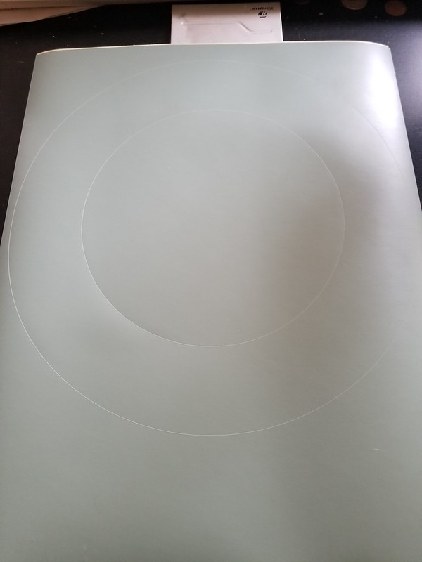
Someone asked me how that works. Well it is about as exciting as watching paint dry but here it is. A stepper motor basically follows a path determined by the software.
I was in the middle of blasting some more parts but the water in the line froze and I was not able to get sufficient pressure so we will wait for those hoses to warm up and dry out.
I had previously media blasted some parts so I thought it would be a good day to powder coat them.
...and 20 minutes later.
While the parts were curing I made up a mask for the brake rotors on my vinyl cutter. This way I can protect the braking surface when I powder coat them. I could have just taped them off but the OCD in me was always bothered by the fact that the powder would not be a perfect circle in the middle. This eliminates that problem.
Someone asked me how that works. Well it is about as exciting as watching paint dry but here it is. A stepper motor basically follows a path determined by the software.
I was in the middle of blasting some more parts but the water in the line froze and I was not able to get sufficient pressure so we will wait for those hoses to warm up and dry out.
Tech Contributor
Joined: Aug 1999
Posts: 15,188
Likes: 4,010
From: Connecticut, USA
Mike
I used a 5 pounder on our original L82 manifolds years ago. Everyone of the bolts were seized sold, tried different things like heat, sprays, candle wax but have to say the 5 lbs really did the trick. I didn't go to the extreme you did with the cutter, just a couple of wacks and into the scrap barrel, the bolts unscrewed great on the manifold was out of the way!!!!!LOL call me Bubba!
I will be watching to see how your line dryer works, I may have to build one of those too.
Thread Starter
Burning Brakes
Joined: Sep 2017
Posts: 1,219
Likes: 365
From: Tolland CT
Thread Starter
Burning Brakes
Joined: Sep 2017
Posts: 1,219
Likes: 365
From: Tolland CT
I am beginning to notice a pattern here: my hands are killing me but I have stuff to do...I have another surgery in a few weeks and who knows how long it will be before I can use my hand at all so I am trying to get as much done as possible.
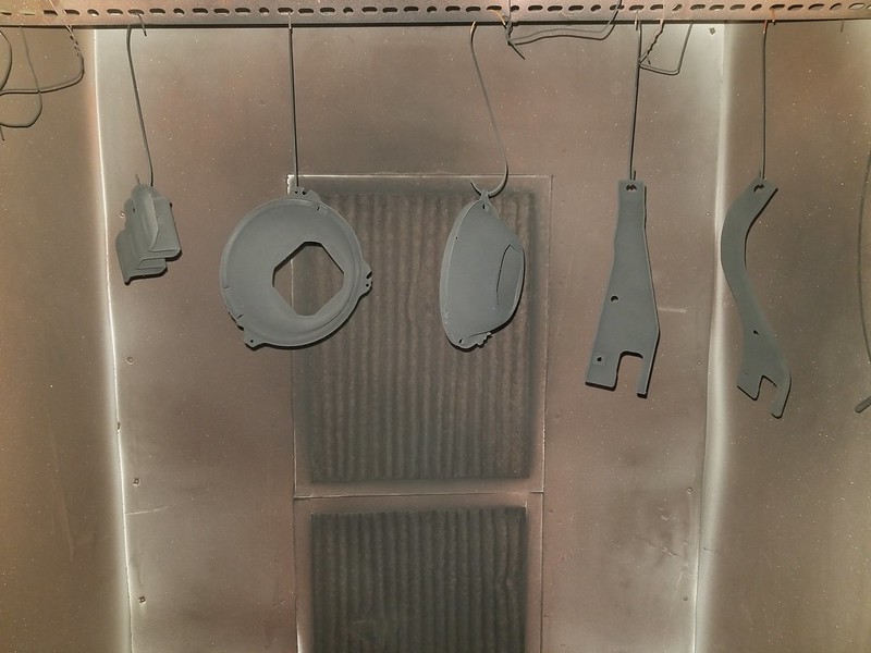
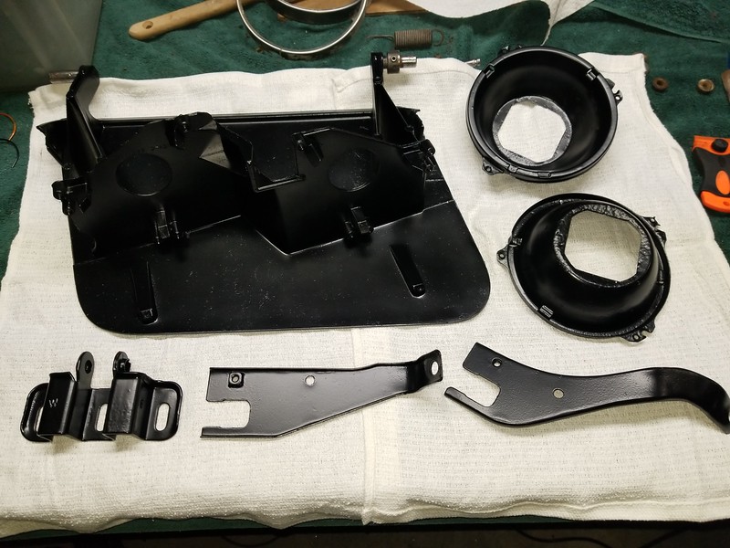
Nothing too glamorous (or strenuous) today. Just cleaning up all the various small bits for one of the headlight assemblies. Blasted, phosphate, and prepared for powder. This method really gives a remarkable finish. These look brand new.
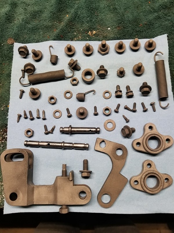
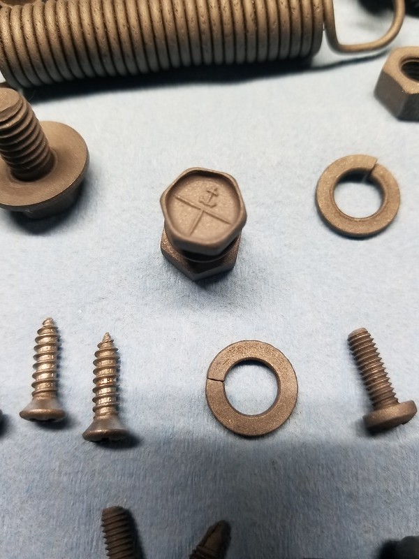
Notice the high quality jig that I made for the springs. It is important to make sure that the powder gets in between the coils to keep them from further corrosion.
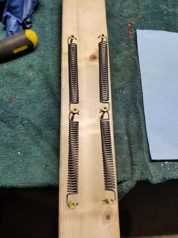
Nothing too glamorous (or strenuous) today. Just cleaning up all the various small bits for one of the headlight assemblies. Blasted, phosphate, and prepared for powder. This method really gives a remarkable finish. These look brand new.
Notice the high quality jig that I made for the springs
. It is important to make sure that the powder gets in between the coils to keep them from further corrosion.
2026 Loser of the Year


Joined: Sep 2013
Posts: 36,607
Likes: 7,053
From: New Or-leens Loo-z-anna
Pat.#10987654321 I an see why you are trying to get a lot done....that's how I have to do it. You're going to have a lot of "New" hardware to install when your hands get better!
