Dragvette Before and After Pics
#21
Itís very close. Itís something I too am concerned about. The tighter the bolts are screwed the flatter the spring became. Iím hoping Iím past the 1/2Ē recomended offset between the upper u-joint and lower u-joint and can loosen the nuts some. Monday a lot of questions will be answered.
#22
Instructor


Thread Starter
Member Since: Aug 2017
Location: New Braunfels Texas
Posts: 133
Likes: 0
Received 5 Likes
on
5 Posts
Maybe my suspension needs to settle. I havenít driven it yet. I was just happy that both sides were equal. The shocks were dialed in at 10 clicks. Maybe I need to drop to 0, let it settle and then dial them back up.
#23
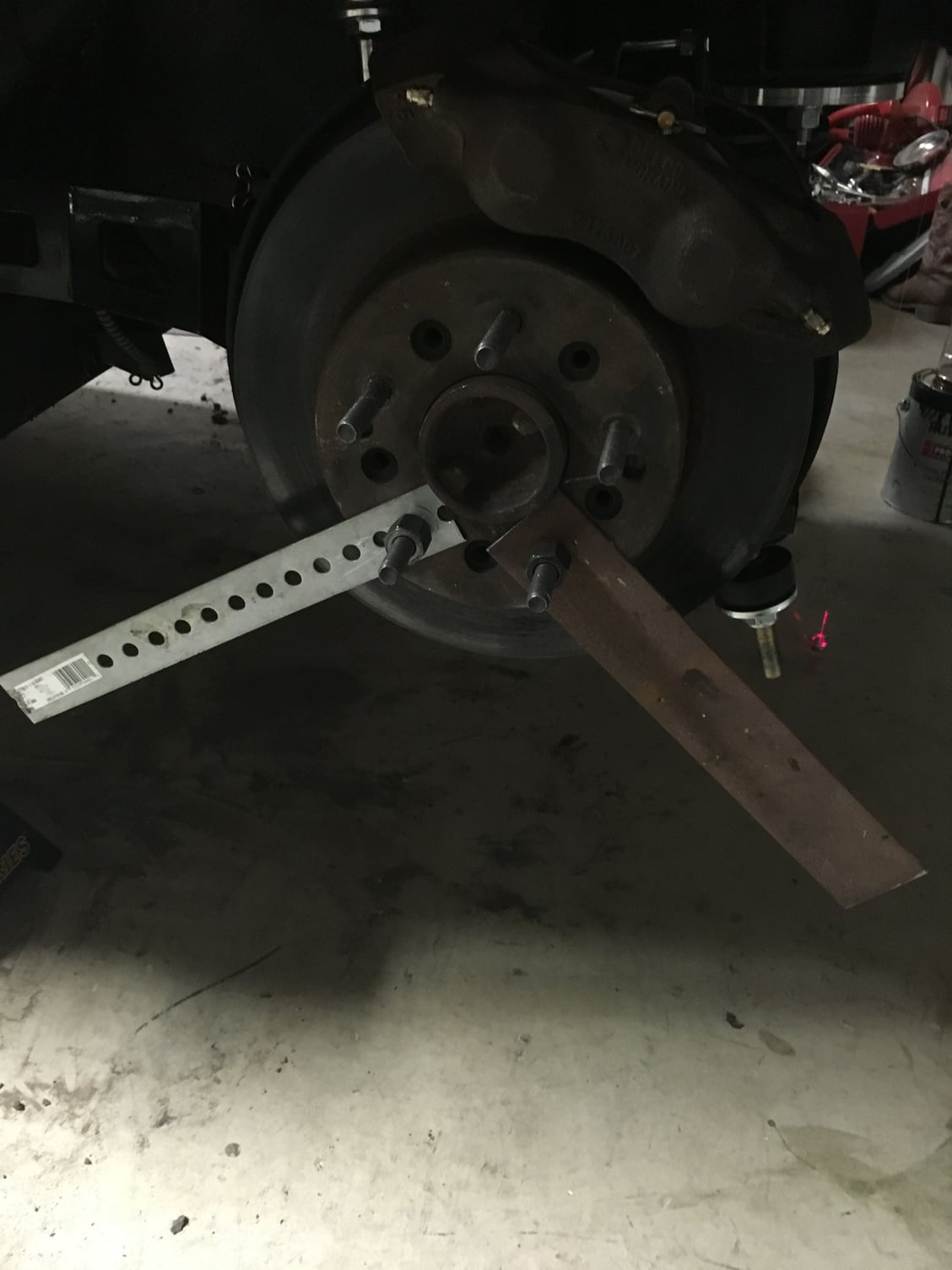
Very nice. Iím going to go with the Rival S also. What backaspaing you running. When I pulled the c clips I slipped the side yokes out until I had about an 1/8Ē still past the spider gears. That allowed about 1/3Ē of side yoke outside the diff. Should translate to a bit more room. I took a piece of flat steel and drilled a hole in it and I I mount it on the rotor. Then I can spin it around and measure to the frame to get my max BS. Iíve been crunching numbers using specs from Tire Trac to find total backspacing (backspacing of the wheel + overhang of the tire).

#24
Instructor


Thread Starter
Member Since: Aug 2017
Location: New Braunfels Texas
Posts: 133
Likes: 0
Received 5 Likes
on
5 Posts
Thatís awesome. Looks your fenders are stock too. What size tire? Iím looking at a Weld S77 11 x 18 with 5.2Ē or 5.6Ē backspacing. By my calculations a 315/30R18 should fit. I came up with an equation to figure the total backspacing of the tire and wheel together.
(Section Width - Wheel Size) / 2 + Backspacing
so for the Rival S
(12.6 - 11)/ 2 + 5.2 = 6Ē Total BS
or
(12.6 - 11) / 2 + 5.6 = 6.4Ē Total BS
then add whatever clearance you want to run. 1/4Ē or 1/2Ē.
(Section Width - Wheel Size) / 2 + Backspacing
so for the Rival S
(12.6 - 11)/ 2 + 5.2 = 6Ē Total BS
or
(12.6 - 11) / 2 + 5.6 = 6.4Ē Total BS
then add whatever clearance you want to run. 1/4Ē or 1/2Ē.
#25
Thatís awesome. Looks your fenders are stock too. What size tire? Iím looking at a Weld S77 11 x 18 with 5.2Ē or 5.6Ē backspacing. By my calculations a 315/30R18 should fit. I came up with an equation to figure the total backspacing of the tire and wheel together.
(Section Width - Wheel Size) / 2 + Backspacing
so for the Rival S
(12.6 - 11)/ 2 + 5.2 = 6Ē Total BS
or
(12.6 - 11) / 2 + 5.6 = 6.4Ē Total BS
then add whatever clearance you want to run. 1/4Ē or 1/2Ē.
(Section Width - Wheel Size) / 2 + Backspacing
so for the Rival S
(12.6 - 11)/ 2 + 5.2 = 6Ē Total BS
or
(12.6 - 11) / 2 + 5.6 = 6.4Ē Total BS
then add whatever clearance you want to run. 1/4Ē or 1/2Ē.

#26
Instructor


Thread Starter
Member Since: Aug 2017
Location: New Braunfels Texas
Posts: 133
Likes: 0
Received 5 Likes
on
5 Posts
That makes more since. Camera angles are deceiving. Looks awesome. Thereís a car in the big tire combo thread thatís running 315ís on 10Ē wheels with no flairs. 5.25Ē BS. Thatís where I got my inspiration. The tires will stick out of the fenders but I have a 420lb spring and will be running QAís at 10 or higher. Did you try to match the tread width of the tire to the wheel size? Iíve read that a key to getting as much of the tread width to ground contact as possible. The wheel should be a 1/2Ē either direction of the tread width with the same being optimal. Section width doesnít matter except for BS purposes.
#27
Thatís awesome. Looks your fenders are stock too. What size tire? Iím looking at a Weld S77 11 x 18 with 5.2Ē or 5.6Ē backspacing. By my calculations a 315/30R18 should fit. I came up with an equation to figure the total backspacing of the tire and wheel together.
(Section Width - Wheel Size) / 2 + Backspacing
so for the Rival S
(12.6 - 11)/ 2 + 5.2 = 6Ē Total BS
or
(12.6 - 11) / 2 + 5.6 = 6.4Ē Total BS
then add whatever clearance you want to run. 1/4Ē or 1/2Ē.
(Section Width - Wheel Size) / 2 + Backspacing
so for the Rival S
(12.6 - 11)/ 2 + 5.2 = 6Ē Total BS
or
(12.6 - 11) / 2 + 5.6 = 6.4Ē Total BS
then add whatever clearance you want to run. 1/4Ē or 1/2Ē.
#28
Instructor


Thread Starter
Member Since: Aug 2017
Location: New Braunfels Texas
Posts: 133
Likes: 0
Received 5 Likes
on
5 Posts
You just reminded me of that. I knew I was forgetting something. I had laid one of my current wheel/tire combos on the ground and did the math and was coming up with less BS than the equation was giving me. I've been brainstorming for the answer. This is why BS and offset are different. I learned all that once and had forgotten it. Increasing the wheel width by 1" actually makes for less total backspacing. I can't wait to see how much actual BS the car has tomorrow. A 11.5' wheel with 5.6" BS should fit. I don't think a lot of people understand that when you increase wheel width it drives the wheel and tire away from the frame for a wheel with the same BS. Also, section width decreases by .2" for every 1/2" wider you go over what the original section width was determined to be. IE: Section width of 10.5" measured on 10" wheel decreases to a section width of 10.3" on a 10.5" wheel, or 10.1" on an 11" wheel. I got this info from Tire Rack who measures all their tires and posts the results.
#32
Instructor


Thread Starter
Member Since: Aug 2017
Location: New Braunfels Texas
Posts: 133
Likes: 0
Received 5 Likes
on
5 Posts
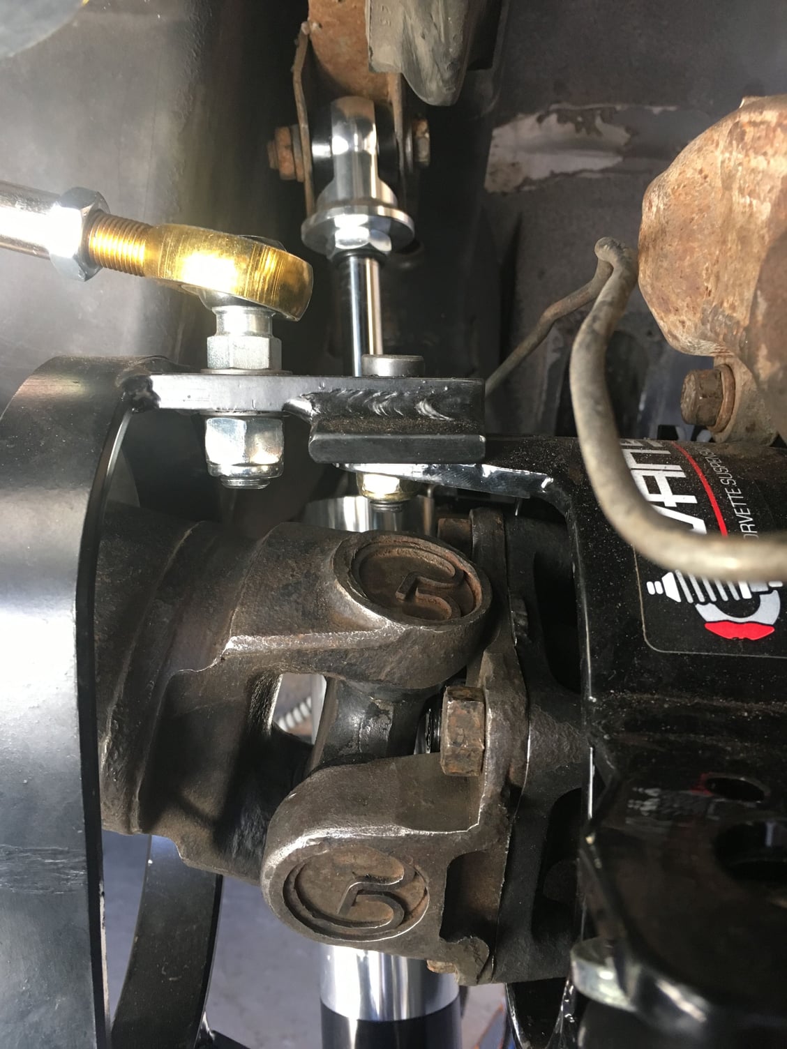
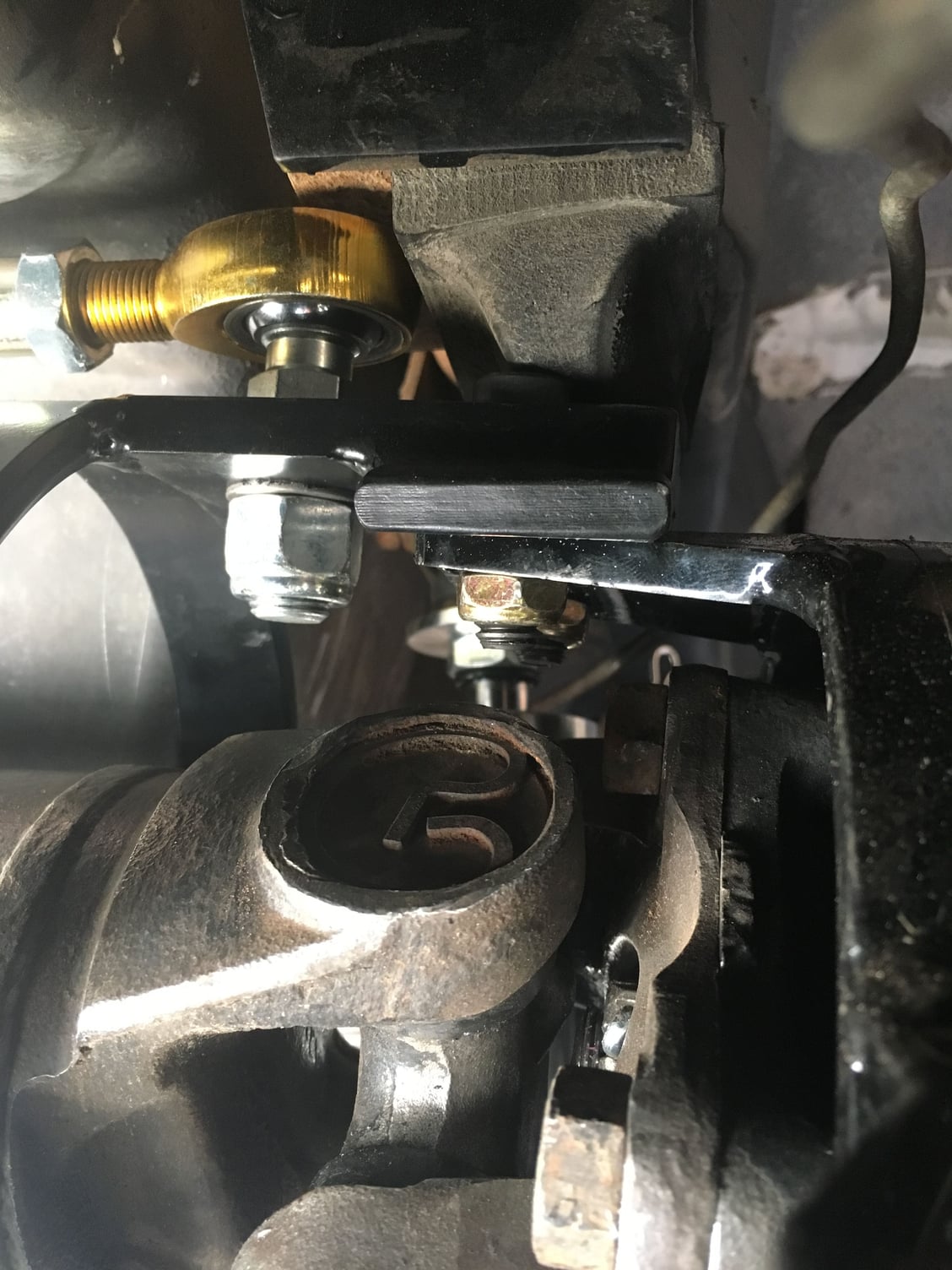
Neil B, Gordonm, as you can see the upper hem will hit the bump stop bracket. The trailing arm simultaneously hits the rubber stopper. The rubber bump stop compressed enough to allow contact. A 1/2Ē spacer would work or I can clearly see that grinding out the part of the bracket that itís hitting would work also. Iíll slap back together, bleed the brakes and drive it as is to see if it hits for me. Iím running a 420 lb spring and the QAís will be set to 10ish. Iíll adjust from there.
Last edited by DIY-79; 01-22-2018 at 03:10 PM. Reason: Spelled members name wrong
#33
Neil B, Gordonm, as you can see the upper hem will hit the bump stop bracket. The trailing arm simultaneously hits the rubber stopper. The rubber bump stop compressed enough to allow contact. A 1/2Ē spacer would work or I can clearly see that grinding out the part of the bracket that itís hitting would work also. Iíll slap back together, bleed the brakes and drive it as is to see if it hits for me. Iím running a 420 lb spring and the QAís will be set to 10ish. Iíll adjust from there.
#34
Instructor


Thread Starter
Member Since: Aug 2017
Location: New Braunfels Texas
Posts: 133
Likes: 0
Received 5 Likes
on
5 Posts
Mine looks like it will only continue up into the actual frame. Iíll check closer to see if I think it will dig into the fiberglass floor. Iím gravity bleeding the brakes as I set the rear toe. I used the center hole of the rear crossmember (not the diff crossmember) as my center point and measured to the backside of the trailing arm to get the lower strut rods set so the rear of the trailing arms are the same distance from the frame centerline. Now Iím setting toe to 0. The camber is already set to 0į. Hopefully Iíll be able to get the rear wheels centered to the frame. Then Iíll use the string method to track the front wheels to the rear. Does this sound like a good plan????
#35
Instructor


Thread Starter
Member Since: Aug 2017
Location: New Braunfels Texas
Posts: 133
Likes: 0
Received 5 Likes
on
5 Posts

Made plumb bobs and dropped them from the center holes in the frame. The specs I have of the frame show those holes as indexed and used for measuring. Now I can set the toe off the line. I used fishing line and what you canít tell from the picture is the laser illuminates the fishing line when itís lined up. I wasnít expecting that, but it made lining the two plumb bobs up a piece of cake.
#36
Instructor


Thread Starter
Member Since: Aug 2017
Location: New Braunfels Texas
Posts: 133
Likes: 0
Received 5 Likes
on
5 Posts

Both sides mirror each other and are same lengths, same angles and same distance from the floor. Iíll check the rear against the laser line and make any fine adjustments using the lower strut rods. Then dial in the toe. Does anyone see any problems with this?????
#37
Mine looks like it will only continue up into the actual frame. Iíll check closer to see if I think it will dig into the fiberglass floor. Iím gravity bleeding the brakes as I set the rear toe. I used the center hole of the rear crossmember (not the diff crossmember) as my center point and measured to the backside of the trailing arm to get the lower strut rods set so the rear of the trailing arms are the same distance from the frame centerline. Now Iím setting toe to 0. The camber is already set to 0į. Hopefully Iíll be able to get the rear wheels centered to the frame. Then Iíll use the string method to track the front wheels to the rear. Does this sound like a good plan????
#38
I usually set the toe with a simple tow bar/gauge. Once toe is where I want it, I use a laser to line up the rear wheels with the front. I shoot a laser from a straightedge along the rear wheel to a fixed point outside of the front spindle. I usually use an index card taped to a jack stand. I adjust toe equally(opposite) on both sides until the laser is equal distance from the front spindle on each side. If this is right, I don't think the relationship between the trailing arms and the frame centerline matters.
The following users liked this post:
Metalhead140 (01-22-2018)
#39
Instructor


Thread Starter
Member Since: Aug 2017
Location: New Braunfels Texas
Posts: 133
Likes: 0
Received 5 Likes
on
5 Posts
I usually set the toe with a simple tow bar/gauge. Once toe is where I want it, I use a laser to line up the rear wheels with the front. I shoot a laser from a straightedge along the rear wheel to a fixed point outside of the front spindle. I usually use an index card taped to a jack stand. I adjust toe equally(opposite) on both sides until the laser is equal distance from the front spindle on each side. If this is right, I don't think the relationship between the trailing arms and the frame centerline matters.
My brain wonít let me not try to index the wheels to the frame. You may be right and it may not matter all that much, as long as the rear tires and front track track the same. I just have to try. I got the toe just shy of 1/8 of an inch. I was able to take her for a drive and sheís very solid. I took the power steering off when I rebuilt the front end. All I have left suspension wise is a spreader bar for the front and tweak the sway bars. Iím waiting to see if I have under or over steer. Then wheels and tires.


