
Oil Catch Can Question...
 11-29-2006, 12:51 PM
#21
Melting Slicks

Thread Starter
Member Since: Jun 2006
Location: Cleveland Tennessee
Posts: 2,923
Likes: 0
Received 1 Like
on
1 Post

This is my installation, I put back the hose from the valve cover to the throttle body. I took the little plastic "U" shaped hose from the PCV valve and installed the hose off the valley pan cover to the side of the oil catch can, then attached the hose from the top of the can to the intake manifold.


 11-29-2006, 04:08 PM
#25
Safety Car

Originally Posted by Dan_the_C5_Man
Not sure I understand your question.. Some pictures are worth a 1,000 words.. It should be clear why the catch-can is where it is. 


Last edited by see5; 11-29-2006 at 04:16 PM.
11-29-2006, 05:39 PM
#26
Team Owner

Originally Posted by jbauch357
This is how I have mine set up, and have approx 1/8" of oil in the can after 1000 miles.

 Same here Josh. The only difference on mine is that I have the can mounted up forward on the inside of the frame rail. I drain approx. 2oz of oil every 4000 miles.
11-29-2006, 05:51 PM
Same here Josh. The only difference on mine is that I have the can mounted up forward on the inside of the frame rail. I drain approx. 2oz of oil every 4000 miles.
11-29-2006, 05:51 PM
#27
Team Owner
Originally Posted by see5
Shown is one of GM's early schemes. It has changed substantially from that schematic. The valley cover vent (LS6), now restricted flow, is new on the LS2s.
Dan's picture shows the earlier version on the hose routing that RonVette2's Z06 does not have. I originally had this set-up but converted over to the "Z06" version a long time ago and in order to do so had to plug the drivers side rear and passenger's side rear fittings on the valve covers and ditch that monstrocity of a pcv hose lash-up that came from GM.  11-29-2006, 05:58 PM
#28
Le Mans Master

O.k., I understand I'm dealing with "outdated technology" , but let's not confuse the issue; the basic theories still apply, i.e. retaining the closed-loop PCV system, inserting the catch-can between the "output" (crankcase) and vacuum (intake manifold), not the "input" (filtered air into the crankcase).
, but let's not confuse the issue; the basic theories still apply, i.e. retaining the closed-loop PCV system, inserting the catch-can between the "output" (crankcase) and vacuum (intake manifold), not the "input" (filtered air into the crankcase).
Last edited by Dan_the_C5_Man; 11-30-2006 at 04:47 PM.
11-29-2006, 06:09 PM
#29
Team Owner
Originally Posted by Dan_the_C5_Man
O.k., I understand I'm dealing with "outdated technology" , but let's not confuse the issue; the basic theories still apply, i.e. retaining the closed-loop PCV system, inserting the catch-can between the "output" (crankcase) and vacuum (intake manifold), not the "input" (filtered air into the crankcase).
, but let's not confuse the issue; the basic theories still apply, i.e. retaining the closed-loop PCV system, inserting the catch-can between the "output" (crankcase) and vacuum (intake manifold), not the "input" (filtered air into the crankcase). Correctmundo! I sometimes almost forget too that some of the newer C5 owners that ask questions regarding the C5 set-up is quite often based on what they have on their car and they assume that their set-up is the way all C5s are. Thanks Dan
11-30-2006, 12:17 AM
#30
Team Owner
Originally Posted by Dan_the_C5_Man
O.k., I understand I'm dealing with "outdated technology" , but let's not confuse the issue; the basic theories still apply, i.e. retaining the closed-loop PCV system, inserting the catch-can between the "output" (crankcase) and vacuum (intake manifold), not the "input" (filtered air into the crankcase).
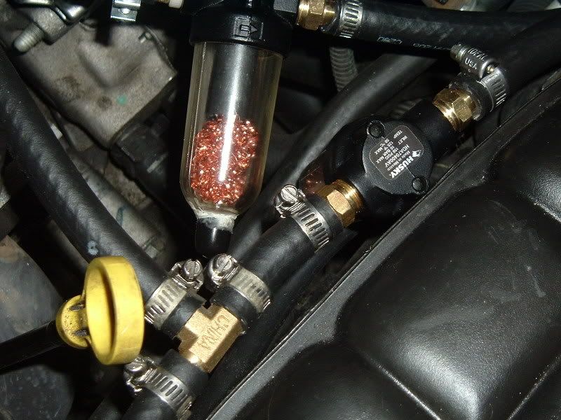
, but let's not confuse the issue; the basic theories still apply, i.e. retaining the closed-loop PCV system, inserting the catch-can between the "output" (crankcase) and vacuum (intake manifold), not the "input" (filtered air into the crankcase).So I run a little Husky (modified) in the fresth air line. And a AMW and a Husky in the line to the intake manifold which is the main culprit.
Here is my customized filter. It should trap MOST oil vapor. Flow is down thru 3/8 hose attached to where the stone filter was removed...into and thru the mesh....then back out the top.
DH
11-30-2006, 11:48 AM
#31
Race Director

Originally Posted by Dan_the_C5_Man
Yikes! It looks cleaner in person, I promise!
[img]http/d/a/dansmallwood/catch_can.jpg[/img]
[img]http/d/a/dansmallwood/catch_can.jpg[/img]
So your stating that if I route the hoses per the instructions, I can still have oil run into the intake?
 11-30-2006, 12:06 PM
#32
Le Mans Master
Not necessarily.. The installation of ANY catch-can between the PCV and intake is better than none at all.
What I'm saying is it makes common sense to force the oil / oil-filled vapors to make a 180 degree turn, go vertical before hitting the intake, vs. the suggested method supplied with the catch-can instructions, where the vapors could potentially make their way to the side vent.
Honestly, you'd probably have a hard time measuring a difference between the two routing schemes; do what you think is logical.
11-30-2006, 01:03 PM
#33
Race Director
Originally Posted by Dan_the_C5_Man
Not necessarily.. The installation of ANY catch-can between the PCV and intake is better than none at all.
What I'm saying is it makes common sense to force the oil / oil-filled vapors to make a 180 degree turn, go vertical before hitting the intake, vs. the suggested method supplied with the catch-can instructions, where the vapors could potentially make their way to the side vent.
Honestly, you'd probably have a hard time measuring a difference between the two routing schemes; do what you think is logical.
What I'm saying is it makes common sense to force the oil / oil-filled vapors to make a 180 degree turn, go vertical before hitting the intake, vs. the suggested method supplied with the catch-can instructions, where the vapors could potentially make their way to the side vent.
Honestly, you'd probably have a hard time measuring a difference between the two routing schemes; do what you think is logical.
11-30-2006, 01:25 PM
#34
Dan,
Does it make a difference having the PCV valve mounted on the Intake side or on the Valley Cover side?
If yes what is according to your test the best place?
Christian
Does it make a difference having the PCV valve mounted on the Intake side or on the Valley Cover side?
If yes what is according to your test the best place?
Christian
11-30-2006, 01:29 PM
#35
Melting Slicks
Thread Starter
Member Since: Jun 2006
Location: Cleveland Tennessee
Posts: 2,923
Likes: 0
Received 1 Like
on
1 Post
It looks like most, me included have left the PCV valve in its original place which I believe is attached to the intake manifold, I too have intalled the intake hose to the top of my oil catach can, and the hose from the valley pan cover to the side of the oil catch can, pictures above.
11-30-2006, 03:08 PM
#36
Le Mans Master
Originally Posted by miami993c297
Dan,
Does it make a difference having the PCV valve mounted on the Intake side or on the Valley Cover side?
If yes what is according to your test the best place?
Christian
Does it make a difference having the PCV valve mounted on the Intake side or on the Valley Cover side?
If yes what is according to your test the best place?
Christian
11-30-2006, 03:35 PM
#37

Mine should be arriving today and after reading his thread Im not sure how I will be installing it yet. it makes perfect sense though to have the top fitting as the outlet going to pcv valve/intake and the side fitting as the inlet from the valley pan.
11-30-2006, 03:46 PM
#38
Originally Posted by Dan_the_C5_Man
Logically I can't see it making any difference what-so-ever, vacuum should be identical, so whatever works for you..
Christian
11-30-2006, 04:37 PM
#39
Le Mans Master
Member Since: Feb 2003
Location: Memphis Tennessee
Posts: 6,670
Likes: 0
Received 135 Likes
on
84 Posts

I admit I am tired right now, but you guys have confused the HECK out of me.
I have mine routed as such:
I took the short line that led from the PCV valve to the TB, led that line to the filter, then the return leads back to where the original line went into the TB. I get a bit of oil, but never more that an ounce or so.
Is mine correct?
I have mine routed as such:
I took the short line that led from the PCV valve to the TB, led that line to the filter, then the return leads back to where the original line went into the TB. I get a bit of oil, but never more that an ounce or so.
Is mine correct?
11-30-2006, 04:43 PM
#40
Le Mans Master
Originally Posted by ALLEGRO
I admit I am tired right now, but you guys have confused the HECK out of me.
I have mine routed as such:
I took the short line that led from the PCV valve to the TB, led that line to the filter, then the return leads back to where the original line went into the TB. I get a bit of oil, but never more that an ounce or so.
Is mine correct?
I have mine routed as such:
I took the short line that led from the PCV valve to the TB, led that line to the filter, then the return leads back to where the original line went into the TB. I get a bit of oil, but never more that an ounce or so.
Is mine correct?
You say "short line from PCV to TB" (throttle-body), when what I believe you really meant to say is "short line from PCV to intake manifold".
If you review the pictures posted in this thread, do they match your configuration?