
Oil Catch Can Question...
 11-30-2006, 04:53 PM
#41
Le Mans Master

Member Since: Feb 2003
Location: Memphis Tennessee
Posts: 6,670
Likes: 0
Received 135 Likes
on
84 Posts

On my '03 AE, the PCV valve is located very near the TB. There is a short line (four inches or so) that leads from the valve to the TB. I used that as my splice. Does that make it easier to understand?
 11-30-2006, 05:00 PM
#42
Le Mans Master

Review the picture in post #7..
In the very top right hand-side, that is the "TB" line.. Just below that and to the left, is the "intake" port.
Catch-can should be inserted into the "intake" port loop, not the "TB" loop.
If this isn't clear, could you post a pic?
Now that I'm thinking, I do believe I've seen your config on 03's and 04's.. If you could post a picture or email, that would be helpful. teamsfr@bellsouth.net
Check out this link, lots of good info. http://eliteengineeringusa.com/Insta...uctions_CC.pdf
Last edited by Dan_the_C5_Man; 11-30-2006 at 05:18 PM.
 11-30-2006, 10:50 PM
#43
Le Mans Master
Member Since: Feb 2003
Location: Memphis Tennessee
Posts: 6,670
Likes: 0
Received 135 Likes
on
84 Posts
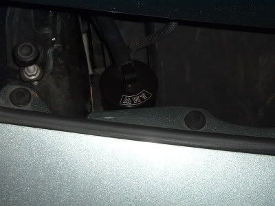
Here's my set up.
The best description I can give you is that the plastic line from the back of the intake manifold leads (eventually) to a rubber line and to the PCV valve. Then from the valve it (used to) lead into the TB. I ran hoses from the PCV to the can and then back to the TB.


The best description I can give you is that the plastic line from the back of the intake manifold leads (eventually) to a rubber line and to the PCV valve. Then from the valve it (used to) lead into the TB. I ran hoses from the PCV to the can and then back to the TB.
12-01-2006, 10:53 AM
#44
Le Mans Master
From what I can see it looks correct, i.e. PCV valve > input of catch-can > output of catch-can > nipple on intake manifold.
TB hose not involved at all.
I would say be careful with the type and length of hose in use; you want minimum restriction, hoses that will not collapse under vacuum and heat, esp. in the sharp turn coming out of the PCV valve.
TB hose not involved at all.
I would say be careful with the type and length of hose in use; you want minimum restriction, hoses that will not collapse under vacuum and heat, esp. in the sharp turn coming out of the PCV valve.
12-01-2006, 11:18 AM
#45
Safety Car

Just so you know this is the latest (~90days) GM recommended PCV "valve" for LSx engines. It is a hollow shell with a ~2mm hole in the big end.
Don't expect much flow.

Don't expect much flow.
12-01-2006, 11:43 AM
#46
Le Mans Master
Interesting.. You are saying this is the "replacement part" if I walk up to the parts counter at a GM dealership (never happen ) and ask for a PCV valve for my 2000?
) and ask for a PCV valve for my 2000?
12-01-2006, 12:27 PM
#47
Team Owner

Originally Posted by see5
Just so you know this is the latest (~90days) GM recommended PCV "valve" for LSx engines. It is a hollow shell with a ~2mm hole in the big end.
Don't expect much flow.
Don't expect much flow.
DH
12-01-2006, 01:03 PM
#49
Le Mans Master
Done (at least enough research to get the point).
Here is my opinion..
This new PCV design is a feeble attempt to accomplish what we are already doing, i.e. installing a catch-can. Severly restricting the flow in an attempt to regulate oil into the intake doesn't seem like the best method.
My vote is "maximum flow, standard PCV valve with a catch-can".
12-01-2006, 03:17 PM
#50
Melting Slicks

Thread Starter
Member Since: Jun 2006
Location: Cleveland Tennessee
Posts: 2,923
Likes: 0
Received 1 Like
on
1 Post

I agree with Dan, I too have sone some research and found that the way we have decided to handle the issue was to get and install these catch cans, and hook them up the way that we did. 
12-01-2006, 03:29 PM
#51
Race Director

Originally Posted by ALLEGRO
Here's my set up.
The best description I can give you is that the plastic line from the back of the intake manifold leads (eventually) to a rubber line and to the PCV valve. Then from the valve it (used to) lead into the TB. I ran hoses from the PCV to the can and then back to the TB.
The best description I can give you is that the plastic line from the back of the intake manifold leads (eventually) to a rubber line and to the PCV valve. Then from the valve it (used to) lead into the TB. I ran hoses from the PCV to the can and then back to the TB.
Also, I measured flow through the PCV line and saw approx. 36 LPM. With vacuum pressure at 20"Hg, these parameters constitute a low flow, low pressure condition. An effective filter should be sized accordingly. I selected a coalescing filter with zinc bowl, but due to its small, 1 oz capacity, made my own extended length bowl out of aluminum. I will post pics, soon. I did select the battery area, too, and the only thing I don't like about this is the need for the inlet hose to loop upward. Liquid oil can be trapped in the loop. Currently, I am testing this setup and may reroute the filter if oil is piling up at the bottom of the loop.
Dave
12-01-2006, 05:28 PM
#53
Team Owner
Originally Posted by Dave68
A word of caution about using commercial particulate filters with polycarbonate bowls: These filter assemblies are typicated temperature-rated to 120 or 125F. The engine bay area where most catch cans are mounted gets up past 140F. Even the battery area, which is cooler, gets up past 130F. What can happen is that the bowl material can creep, compromising its sealing ability.
Also, I measured flow through the PCV line and saw approx. 36 LPM. With vacuum pressure at 20"Hg, these parameters constitute a low flow, low pressure condition. An effective filter should be sized accordingly. I selected a coalescing filter with zinc bowl, but due to its small, 1 oz capacity, made my own extended length bowl out of aluminum. I will post pics, soon. I did select the battery area, too, and the only thing I don't like about this is the need for the inlet hose to loop upward. Liquid oil can be trapped in the loop. Currently, I am testing this setup and may reroute the filter if oil is piling up at the bottom of the loop.
Dave
I am keeping an eye on my cheepo-carbonate-creeping filters. So far they seem very intact, screwing in and out without binding or any signs of creep.

Why don't you mount your can to the right side frame up front as I and others have done?? Its cooler and a down hill run from intake to can.

DH
12-01-2006, 10:32 PM
#54
Melting Slicks
Originally Posted by Dirty Howie
Dave
I am keeping an eye on my cheepo-carbonate-creeping filters. So far they seem very intact, screwing in and out without binding or any signs of creep.
Why don't you mount your can to the right side frame up front as I and others have done?? Its cooler and a down hill run from intake to can.
DH
I am keeping an eye on my cheepo-carbonate-creeping filters. So far they seem very intact, screwing in and out without binding or any signs of creep.
Why don't you mount your can to the right side frame up front as I and others have done?? Its cooler and a down hill run from intake to can.
DH
FRED
12-02-2006, 12:08 AM
#55
Race Director
Originally Posted by Dirty Howie
Dave
I am keeping an eye on my cheepo-carbonate-creeping filters. So far they seem very intact, screwing in and out without binding or any signs of creep.
Why don't you mount your can to the right side frame up front as I and others have done?? Its cooler and a down hill run from intake to can.
DH
I am keeping an eye on my cheepo-carbonate-creeping filters. So far they seem very intact, screwing in and out without binding or any signs of creep.
Why don't you mount your can to the right side frame up front as I and others have done?? Its cooler and a down hill run from intake to can.
DH
I'm sure there is a safety factor in that max temp, but it's kinda like using radiator hose when you need fuel line hose. You might be able to have no issues for a year, a month, or ?????
I may very well change my location just because of the downhill factor. The battery compartment makes removing the can a breeze; how is it when it's mounted down low? Is it a pain to get to when you have the back of a 48 year-old?
Ron, Here's a pic of my custom extended can. It quadruples the oil capacity of the original.
 12-02-2006, 12:57 AM
#56
Team Owner
Originally Posted by FRED HAMBLE
Do you have a pic of this ? Would like to see where you installed the can. I have the Chrome tension cover which interfers with the standard installation.
FRED
FRED
DH
12-02-2006, 01:02 AM
#57
Team Owner
Originally Posted by Dave68
Howie,
I'm sure there is a safety factor in that max temp, but it's kinda like using radiator hose when you need fuel line hose. You might be able to have no issues for a year, a month, or ?????
I may very well change my location just because of the downhill factor. The battery compartment makes removing the can a breeze; how is it when it's mounted down low? Is it a pain to get to when you have the back of a 48 year-old?
Ron, Here's a pic of my custom extended can. It quadruples the oil capacity of the original.
Quit your bitchin.......I'm 56 so I'm sure you can handle it
You get on your knees, pull hoses, loose allen screw which keeps can in bracket, pull can ........ 75 seconds max
Your can looks very small or you have a huge freakin hand...
DH
12-02-2006, 01:24 AM
#58
Le Mans Master
Dave has access to CAD/CAM and milling machines, so it looks like he made a small aluminum can to replace the small plastic / glass unit on the air compressor filter.
If I had access to the tools and machines Dave does, hell, my wife and kids would only see me twice a day, once to eat and once to (eventually) sleep.
If I had access to the tools and machines Dave does, hell, my wife and kids would only see me twice a day, once to eat and once to (eventually) sleep.
12-02-2006, 02:01 PM
#59
Le Mans Master
Member Since: Feb 2003
Location: Memphis Tennessee
Posts: 6,670
Likes: 0
Received 135 Likes
on
84 Posts
I finally found a diagram of the PCV system.
What I did is spice my can line at the front of the PCV valve and routed it back into the TB.
Maybe this diagram helps to understand my install better.
Comments??

What I did is spice my can line at the front of the PCV valve and routed it back into the TB.
Maybe this diagram helps to understand my install better.
Comments??
12-02-2006, 04:37 PM
#60
Le Mans Master
Barry, I think we keep saying the same thing, but using different terminology..
The line with the PCV valve should have been connected to the intake nipple, not the throttle-body nipple, before you installed the catch-can. The diagram you posted shows the PCV valve terminating to the intake nipple. Do you agree? Did you but the car new or used?
Again, it should go valley cover / crankcase > PCV valve (either before or after the valve, makes no difference), > catch-can > intake manifold.
You should have a separate hose from the throttle-body to (I presume on your car) a nipple on a valve cover.
If you have it routed valley cover / crankcase > PCV valve > catch-can > throttle-body nipple, then you have disconnected the fresh air supply to the crankcase, and it must be hanging open somewhere un-filtered (not good).
No worries; the picture you posted clearly shows you have the catch-can in the correct location, you just need to understand the black plastic nipple is from the intake manifold, not the throttle-body (that's the aluminum nipple).
Last edited by Dan_the_C5_Man; 12-02-2006 at 04:43 PM.