


COMP Rocker Trunion Install
Thread Starter
Burning Brakes


Joined: Jun 2005
Posts: 782
Likes: 45
From: Toronto Ontario
I finally got around to installing these things and thought I'd share what learned. I don't think I've poured enough spinach into my motor to warrant spending a boat-load of money on new rockers, but I don't like the idea of finding needles from my rocker arms stuck to my drain plug either. In my humble opinion, the factory arms are actually quite nice ...they just need better bearings to make them great!
Enough talk...Here's what it took to do this:

This is what the UPS guy showed up with.
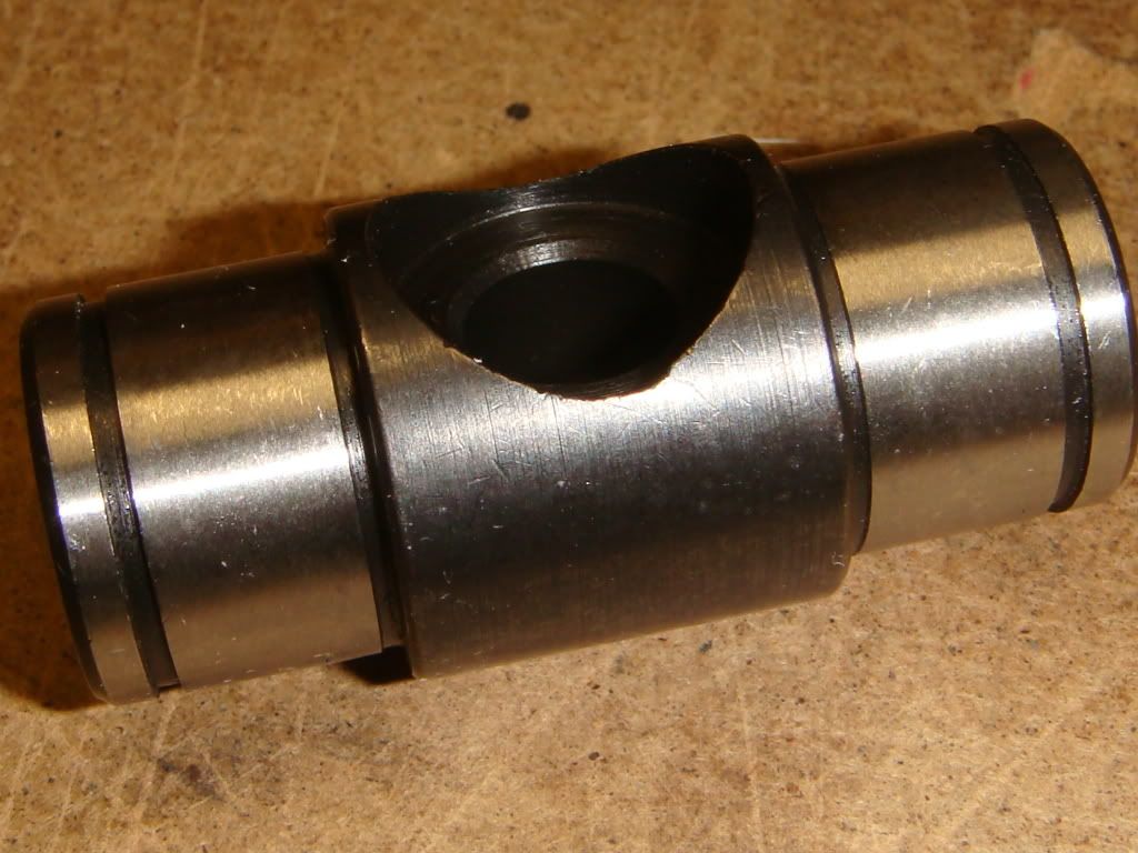
This is a close-up of the new trunion shaft with it's cylindrically ground inner races.
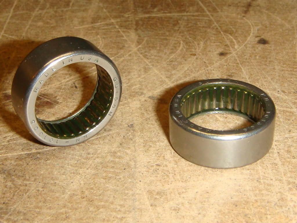
And here's a close-up of the new bearings. 33 rollers, same as OEM.
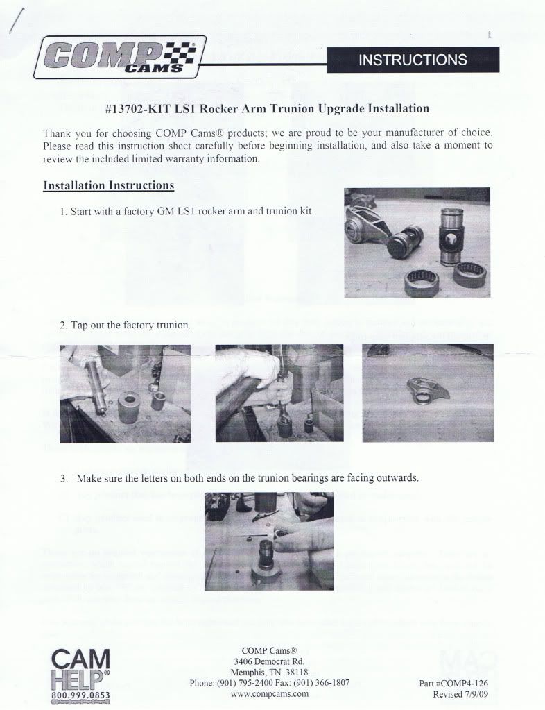
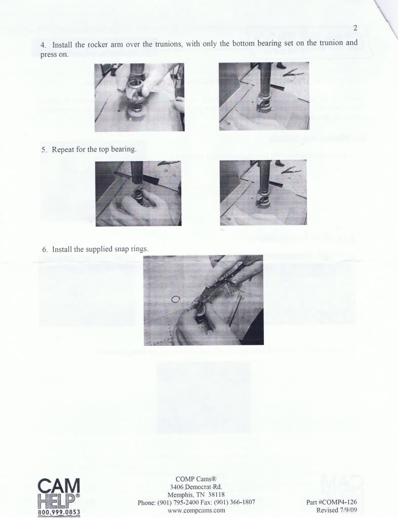
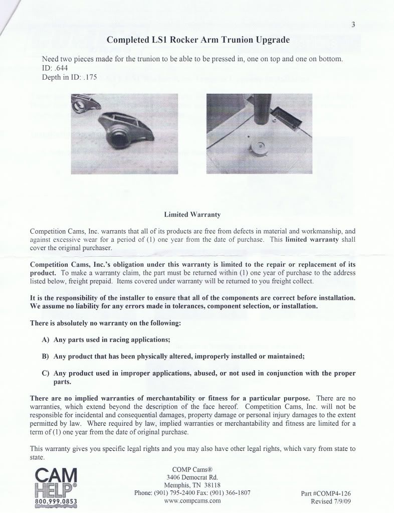
Instructions that were included with the kit.

This is what the arm looks like straight off the engine, with it's OEM trunion. GM apparently changed the trunion design in 2002 to fix the problem they had where the needles could fall out. I've never seen a picture of the original design, but I suspect that this is one of the first of the new breed. The needles look fairly well contained.

This is the lower supporting block I used to press the old bearings into. Its about 2" high, and has a 7/8 hole through it. The top surface is made of bronze so it wouldn't mark the arm, but this probably isn't necessary. The outside diameter of the bearing is .814, so you could press them into a 13/16 socket as well.

Pressing the factory trunion out. I used a 5/8" diameter punch on top, but anything up to about .8" would work. You only have to push it down about 3/8" before it all falls out. If you look closely, you'll notice that one side of the arm has more flat surface on it than the other. That's the side I laid it down on. I used a small hydraulic press for this, but you could probably use a bench vice as well if you have a helper and some patience. The important thing is to make sure everything lines up before you give 'er.

These are the guts that fell out the bottom. The inner and outer races are made from stamped steel, with 33 needles in between. The trunion shaft looks like it might be investment cast, like the rocker. One thing I noticed right away is a huge amount of radial play (maybe .030) between the shaft and the inner race pieces. The shaft isn't machined here, so maybe they made it a little loose to ensure that it fit? Don't know, but it's the same on all 32 of them. The needles in the replacement bearings ride directly on the ground surface of the shaft and have no noticable play in them.

Here's what the rocker arm looks like with everything removed.

This is the installation block mentioned in the instructions. It supports the shaft and first bearing while the arm is being pressed down. I made the hole 5/8" diameter, .165 deep. Having one of these makes this project a breeze, but its not required. You can do this with a 5/8" socket too, but this is more stable and probably easier in the end. It's important to note that the bearing sits on the top surface...the shaft poking thru the bearing hangs down into the hole but doesn't touch the bottom. The hole has to be AT LEAST .165 deep, but it could go all the way thru if you want. Just make sure the shaft doesn't bottom out in the hole.

Here I've slid the first bearing onto the trunion, and now it's ready to go onto the installation block in the background. Before you slide the bearing on, take a look inside and make sure all the rollers are present and accounted for. The only thing holding them in is the grease! I wouldn't want to do this 16 times and then find a couple of extra rollers at the bottom of the bag.

All we need is a rocker arm...

The rocker arm is sitting in position over the trunion and the press is starting to come down to push it onto the first bearing. I used a 1" diameter punch with a 5/8" hole in the center. When the arm gets pushed down, the shaft will start to poke out the top, and the hole gives it somewhere to go. I used copper so that it wouldn't mark the arm, but again this probably wasn't necessary. The press fit isn't really that killer. The important thing here is that you PRESS THE BEARING IN FLUSH WITH THE ARM. This support block won't let it go in any further, but a socket might. If it goes in too deep, the rollers will bind against the inner edge of the shaft when the second bearing is installed.

With the lower bearing in place, the upper bearing can be pressed in. Same thing...make sure you push it in flush with the arm, and no deeper. Also...remember to check that all the rollers are there!

All that's left to do is install the two circlips. It's interesting to note that nothing ever comes into contact with these clips. They're just an insurance policy in case the bearings ever work free from the arm. I suspect that this might be one mode of failure for the OEM pieces. There's nothing really stopping the outer races from gradually working themselves out of their bores. Just speculating, though.

Finished!

Enough talk...Here's what it took to do this:
This is what the UPS guy showed up with.
This is a close-up of the new trunion shaft with it's cylindrically ground inner races.
And here's a close-up of the new bearings. 33 rollers, same as OEM.
Instructions that were included with the kit.
This is what the arm looks like straight off the engine, with it's OEM trunion. GM apparently changed the trunion design in 2002 to fix the problem they had where the needles could fall out. I've never seen a picture of the original design, but I suspect that this is one of the first of the new breed. The needles look fairly well contained.
This is the lower supporting block I used to press the old bearings into. Its about 2" high, and has a 7/8 hole through it. The top surface is made of bronze so it wouldn't mark the arm, but this probably isn't necessary. The outside diameter of the bearing is .814, so you could press them into a 13/16 socket as well.
Pressing the factory trunion out. I used a 5/8" diameter punch on top, but anything up to about .8" would work. You only have to push it down about 3/8" before it all falls out. If you look closely, you'll notice that one side of the arm has more flat surface on it than the other. That's the side I laid it down on. I used a small hydraulic press for this, but you could probably use a bench vice as well if you have a helper and some patience. The important thing is to make sure everything lines up before you give 'er.
These are the guts that fell out the bottom. The inner and outer races are made from stamped steel, with 33 needles in between. The trunion shaft looks like it might be investment cast, like the rocker. One thing I noticed right away is a huge amount of radial play (maybe .030) between the shaft and the inner race pieces. The shaft isn't machined here, so maybe they made it a little loose to ensure that it fit? Don't know, but it's the same on all 32 of them. The needles in the replacement bearings ride directly on the ground surface of the shaft and have no noticable play in them.
Here's what the rocker arm looks like with everything removed.
This is the installation block mentioned in the instructions. It supports the shaft and first bearing while the arm is being pressed down. I made the hole 5/8" diameter, .165 deep. Having one of these makes this project a breeze, but its not required. You can do this with a 5/8" socket too, but this is more stable and probably easier in the end. It's important to note that the bearing sits on the top surface...the shaft poking thru the bearing hangs down into the hole but doesn't touch the bottom. The hole has to be AT LEAST .165 deep, but it could go all the way thru if you want. Just make sure the shaft doesn't bottom out in the hole.
Here I've slid the first bearing onto the trunion, and now it's ready to go onto the installation block in the background. Before you slide the bearing on, take a look inside and make sure all the rollers are present and accounted for. The only thing holding them in is the grease! I wouldn't want to do this 16 times and then find a couple of extra rollers at the bottom of the bag.
All we need is a rocker arm...
The rocker arm is sitting in position over the trunion and the press is starting to come down to push it onto the first bearing. I used a 1" diameter punch with a 5/8" hole in the center. When the arm gets pushed down, the shaft will start to poke out the top, and the hole gives it somewhere to go. I used copper so that it wouldn't mark the arm, but again this probably wasn't necessary. The press fit isn't really that killer. The important thing here is that you PRESS THE BEARING IN FLUSH WITH THE ARM. This support block won't let it go in any further, but a socket might. If it goes in too deep, the rollers will bind against the inner edge of the shaft when the second bearing is installed.
With the lower bearing in place, the upper bearing can be pressed in. Same thing...make sure you push it in flush with the arm, and no deeper. Also...remember to check that all the rollers are there!
All that's left to do is install the two circlips. It's interesting to note that nothing ever comes into contact with these clips. They're just an insurance policy in case the bearings ever work free from the arm. I suspect that this might be one mode of failure for the OEM pieces. There's nothing really stopping the outer races from gradually working themselves out of their bores. Just speculating, though.
Finished!
Last edited by Its_Go_Time; Dec 10, 2009 at 06:22 PM.
Thread Starter
Burning Brakes
Joined: Jun 2005
Posts: 782
Likes: 45
From: Toronto Ontario

Safety Car


Joined: Jul 2005
Posts: 3,572
Likes: 9
From: Jackson Tn
St. Jude Donor '06-'07-'08-'09
Great write up
The only thing that might be added is to make sure you use the new bolts supplied in the kit. I remember reading a thread over on LS1Tech about someone not receiving the bolts and when they tried to bolt them up they would not get tight. The original bolts need more threads.
The only thing that might be added is to make sure you use the new bolts supplied in the kit. I remember reading a thread over on LS1Tech about someone not receiving the bolts and when they tried to bolt them up they would not get tight. The original bolts need more threads.
Corvette Stories
The Best of Corvette for Corvette Enthusiasts

5 Best & 5 Worst Corvette Daily Drivers
Joe Kucinski
The Headlights of Every Corvette Generation Explained
Joe Kucinski
5 Best & 5 Most Overrated Corvette Track Packages of All Time!
Joe Kucinski
Every 2027 Corvette Engine Explained
Joe Kucinski
Designer Imagines A Corvette That Looks More Like a Corvette Than the Corvette
Verdad Gallardo
10 Ugly Corvettes That We Still Kinda Love
Joe Kucinski
Top 10 Most Expensive Corvettes Ever Sold on Bring A Trailer
Brett Foote
10 Things Every Corvette Owner Needs (2026 Edition)
Michael S. Palmer
8 Most "Only Corvette Owners Understand" Quirks and Problems
Pouria SavadkoueiRace Director

Joined: Sep 2005
Posts: 11,060
Likes: 291
From: Pasco WA
Great write-up and pictures. However, you have special tools that the average shade-tree guy doesn't, and the trunnion upgrade itself isn't cheap. In the end you still have non roller tip'd rockers, and considerable time/effort. In my case, the HS full rollers were free, but I think they retail for about $300. Money well spent, IMO, versus the trunnion replacement option.
Thread Starter
Burning Brakes
Joined: Jun 2005
Posts: 782
Likes: 45
From: Toronto Ontario
Great write up
The only thing that might be added is to make sure you use the new bolts supplied in the kit. I remember reading a thread over on LS1Tech about someone not receiving the bolts and when they tried to bolt them up they would not get tight. The original bolts need more threads.
The only thing that might be added is to make sure you use the new bolts supplied in the kit. I remember reading a thread over on LS1Tech about someone not receiving the bolts and when they tried to bolt them up they would not get tight. The original bolts need more threads.
My kit didn't come with screws, and they bolted in without any problems. The OEM screws certainly seem long enough...even the screws on valves that were on their lobe got in quite a few turns before the spring started to compress. The hole in the shafts have counterbores for the screw heads...maybe there was some problem with those on LS1Tech guys set?
Safety Car
Joined: Jul 2005
Posts: 3,572
Likes: 9
From: Jackson Tn
St. Jude Donor '06-'07-'08-'09
Anyone doing this mod needs to heed the bolt issue. This could be a really big problem if not caught.
here is a link to the bolt problem thread.
http://www.ls1tech.com/forums/genera...-question.html
here is a link to the bolt problem thread.
http://www.ls1tech.com/forums/genera...-question.html

Tech Contributor


Joined: Dec 1999
Posts: 32,910
Likes: 2,402
From: Anthony TX
CI 6,7,8,9,11 Vet
St. Jude Donor '08
If you add more threads to the bolts OR the bolts need to go further into the head,,,,you will most likely have a bolt sticking down in the intake runner. When I installed my Patriot Stage II ported heads, I had to grind off about 1/8" of the bolt to keep it out of the intake tract. You might want to check that.
Heres where it pokes thru and if ground off it will not effect air flow:

If the aftermarket trunnion has a recess on the top where the bolt head sits on the stock trunnion, the lifter preload and valve lift will be effected and not in a good way.
Bill
Heres where it pokes thru and if ground off it will not effect air flow:
If the aftermarket trunnion has a recess on the top where the bolt head sits on the stock trunnion, the lifter preload and valve lift will be effected and not in a good way.
Bill
Last edited by Bill Curlee; Jan 19, 2010 at 08:36 PM.
Thread Starter
Burning Brakes
Joined: Jun 2005
Posts: 782
Likes: 45
From: Toronto Ontario

OK. I would hate for anyone to mess anything up due to my write-up, so I'm gonna try and add as much information to it as I can. My ride is on stands until spring time, so I took this opportunity to pull the entire passenger rockertrain off for some measurements.
The OEM screws, when used with the COMP trunnions, stick out below the pedestals .990", with threads all the way up.
The OEM screws, when used with the original OEM trunnions, stick out below the pedestals .940", .050" less than above.


The counterbore will have no effect on lifter preload. The only way preload could be changed with the rockers is if the position of the bearing centerline changes (or the rocker ratio is changed).
I will measure the centerline heights of both OEM and COMP trunnions at work tomorrow. It would be hard to believe that COMP would be that dumb, though.
Melting Slicks

Joined: Apr 2006
Posts: 2,151
Likes: 20
I have installed this upgrade as well on my car outlined in another thread and I never gave any thought to the fastener length. Seemed to be ok and with a couple hundred miles so far and some dyno time there are no issues. I did add blue locktite for security.
Someone suggested the roller tip may be better than the non-roller factory arm. FWIW, I've seen yates cup motors and the rockers were ultra trick, lightweight, and had no rollers on the tips. Tip was similar to the factory LS rocker tip. Those motors spare no expense and in many cases turn 10k rpm.
Someone suggested the roller tip may be better than the non-roller factory arm. FWIW, I've seen yates cup motors and the rockers were ultra trick, lightweight, and had no rollers on the tips. Tip was similar to the factory LS rocker tip. Those motors spare no expense and in many cases turn 10k rpm.
Thread Starter
Burning Brakes
Joined: Jun 2005
Posts: 782
Likes: 45
From: Toronto Ontario
To check concerns that proper lifter pre-loads aren't being achieved with these new trunions, I measured the distance between the center of the rocker bearings to the head mounting surface for The OEMers and the COMP pieces.
OEM: .858"
COMP: .854"
The same, so assuming that you don't change anything else in the valvetrain, the preload will remain the same.
I also measured the depth of the threaded holes in my heads. The heads are factory 243 castings, with no porting work done. The holes are all blind...in other words, they don't extend into the runners. Porting might change that, though! The holes are 1.100 deep. So, in my case anyway, there's almost 1/8" to spare at the bottom when the rockers are torqued down.
However, if you do find that you don't have enough thread on the screw, or the screws are too long and bottom out or poke out into a ported runner, here's one possible option. Standard dimension socket head cap screws, M8 x 1.25, 50mm long. The OEM screws are graded as 10.9, but quality screws such as this Holo Krome I liberated from work are grade 12.9. They are .100 shorter, with 1/4 more thread. The head diameters are identical. Perfect.
Safety Car

Joined: May 2007
Posts: 4,812
Likes: 46
From: Taylorsville North Carolina
So what is the final consensus - trim stock bolts or not? I got my used set of rockers arms and have the old trunions removed(snowed in here today). Haven't ordered Comp trunions yet, I was just piddling today getting ready. Going to trim bolts if necessary. I made a wood supporting block and tapped old trunions out. Not sure that will work for install. Tried reinstalling using block and 6" C-clamp but not stable enough. Need to find a creative way to press in without a press. Thoughts?
Tech Contributor


Joined: Jan 2007
Posts: 19,526
Likes: 1,195
From: Dyer, IN
So what is the final consensus - trim stock bolts or not? I got my used set of rockers arms and have the old trunions removed(snowed in here today). Haven't ordered Comp trunions yet, I was just piddling today getting ready. Going to trim bolts if necessary. I made a wood supporting block and tapped old trunions out. Not sure that will work for install. Tried reinstalling using block and 6" C-clamp but not stable enough. Need to find a creative way to press in without a press. Thoughts?
Thread Starter
Burning Brakes
Joined: Jun 2005
Posts: 782
Likes: 45
From: Toronto Ontario
Tech Contributor
Joined: Dec 1999
Posts: 32,910
Likes: 2,402
From: Anthony TX
CI 6,7,8,9,11 Vet
St. Jude Donor '08
If you heat the rockers up to about 200 degrees in the over or with a heat gun and chill the trunnions in the freezer,, you will have a WHOLE lot easier time pressing the trunnions in the rocker. I bet you could use a C clamp and a socket.
Try this. Install a NEW un-installed trunnion on the pedestal with a new and old screw. If there is any lost motion between the trunnion and rocker pedestal, the screw thread isn't long enough or the screw is bottoming out in the threaded hole. I would NOT torque the screw down until you can figure out if the screw is going to bottom out. If it is too long, and you torque it down, you may punch thru the intake runner and drop a piece of aluminum into the cylinder.
Just something to check.