When you click on links to various merchants on this site and make a purchase, this can result in this site earning a commission. Affiliate programs and affiliations include, but are not limited to, the eBay Partner Network.
Looking at Ozwald 25's pictures again, I see the manifold vacuum hose to the top catch can port, no PCV valve and the bottom hose from the catch can going under the throttle body to somewhere.
With no PCV valve, how is the manifold vacuum moderated? Oz thinks this is a PCV delete system.
If the hose under the throttle body simply connects to the driver side valve cover or the valley pan without a PCV valve, there is a vacuum leak which would be big at startup, slowing as the manifold vacuum evacuates the crankcase.
An easy check would be to plug the manifold vacuum source to the catch can and see how it runs.
exactly !!...trying to figure out that �plumbing� !!
Would it be wise to install a new PCV valve in addition to the catch can? I started the car again today and finally codes popped up which were the original 3 I was having difficulty with causing the reduced engine power, the P1516, P1517, and P1518. Seems to me that I need a new TAC module. However I am a bit unsure of what I would need to do for this vacuum leak. As per the Catch can plumbing schematic should I plug off the PCV connection at the back of the Passenger side valve cover? Or is that what v6turbo87 is referring to about the vacuum line for HVAC control?
In my view the catch can diagram with a PCV valve is best (197- 2003 LS1). It provides for filtered air into the engine and then to the PCV valve, then to manifold vacuum.
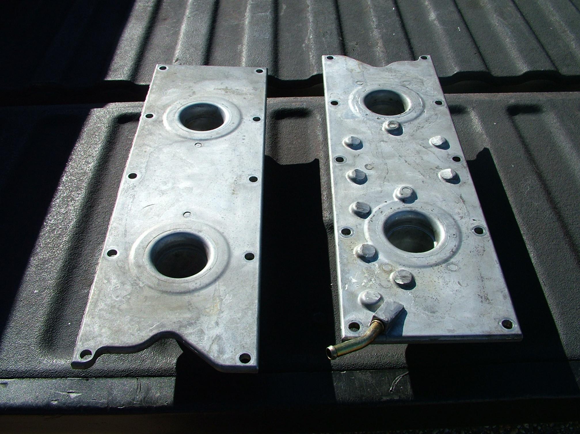
Jim, I was looking at the Elite Engineering schematic and it looked fine..until I realized that the other hose on the catch can is going into a valley cover inlet port. I didnt believe LS1 engines had this so this leads me to believe that this is a LS6 Valley Cover..that seems to just add to the complications LOL. My valley cover looks like the one on the right of this next picture.
Yes that is an LS 6 valley cover on the right. No problem, just plumb with a PCV valve as shown in the Elite Engineering diagram shown for 2001- 2003 LS6 on the top of page 6:
The bottom diagram on page 6 has the PCV valve at the valley cover, which would also work but the PCV valve is harder to access at that location.
With either of the diagrams, only one port on one valve cover is used, the others should be capped securely otherwise unfiltered air will enter the uncapped port(s).
Oz,
I probably wouldn't worry about your PCV system right now since you aren't seeing any lean codes. Maybe clear the DTC's and see what comes back. If all those DTC's come back I would remove the 2 TAC module connectors and check for corrosion and pin fitment (see picture)...If all good and you have a multi meter disconnect the MAF and TPS sensors and with key ON check the 5 volt ref. on those sensors...the yellow wire on the MAF and the dark blue wire on the TPS. If 5 volt ref. good plug them back in and now you can check the TPS voltages. you will need to back probe (see picture) the dark blue wire (TPS1) with voltmeter red lead and black lead to ground. with key ON push the accelerator to the floor....voltage should be 4.09-4.87...if the PCM sees that voltage over 4.87 it sets the P1120 !!....to check TPS 2 connect the red lead to the pink wire...remove TAC motor connector and gain access to the the TB...make sure throttle plate is fully closed. Again with key ON voltage should be 4.3-4.8 with throttle plate closed. If PCM sees higher than 4.87 a P1220 will set. I'm trying to figure out the P0108...if the PCM sees the MAP sensor voltage higher than 4.9 volts it sets the DTC....that's why I want to make sure those 5 volt references are not way higher than 5 volts...the PCM supplies the 5 volts through a regulator to many sensors in the car... all 5 volt ref's will be affected
. Would also be a good idea to get your battery checked out !!
Hey everybody, Its been a hot minute. I have been on Military leave and change of bases. The Corvette has been driving great here lately since I plugged up that vacuum leak with a rubber stopper. Turns out the previous owner had put an LS6 Valley cover in with an integrated PCV system for this LS1. I replaced the knock sensors and the harness and it didnt give me any issues for a couple months. Here lately the Knock sensor codes have been intermittently popping up along with the 3 TAC module codes I got previously (About 2-3 times a week). I clear them because I have not noticed any engine knock or decrease in performance. With one exception however, when the A/C is on and Im cruising around and the car is good and warmed up, occasionally upon downshifting I would push the clutch in to go to 2nd or Neutral and with the clutch in the car bogs down and sometimes dies. Starts right back up no problem but would this still be a symptom of the TAC module?
Thank you! -OZ
You have several issues. Im adding a couple of thing that will help you understand the differences in the TWO PCV system on the LS1 early engines and Late LS1 Engines and or the LS6 engine.
The top schematic is the early LS1 PCV pluming system:
I had to laugh. In the picture that you posted in post 26 that displays the PLUG in the valve cover YES, it plugged off on the second designed PCV system, you also show the top of the engine (drivers side) WIRING HARNESS. There is a BLACK METAL bracket that the harness bends around. That bracket is a SAFETY STOP for the fuel rail to keep it from sheering off in an accident.
If your harness RUBS on that bracket, and chafes the wires inside, you can short out whatever is damaged against that metal bracket or between the wires in the harness.
GUESS WHAT RUNS THROUGH THAT HARNESS??? ALL of the things that you are having issues with.
YES,,, I've seen 7 or 8 C5s that this has been an issue with. Some worse than others.
IMHO, I would unwrap that harness and inspect those wires.
Here is what it looks like at the rub zone:
Last edited by Bill Curlee; May 20, 2019 at 05:02 PM.


 ALL of the things that you are having issues with.
 I've seen 7 or 8 C5s that this has been an issue with. Some worse than others.