When you click on links to various merchants on this site and make a purchase, this can result in this site earning a commission. Affiliate programs and affiliations include, but are not limited to, the eBay Partner Network.
I havent seen many threads on solid axle swaps on this forum. Anyone else gone crazy and converted to solid axle? I've seen lots of older vettes, a handful of C5's and one or two C6's converted as shown below. Does anyone know if those cars have run yet? I know one guy was chatting up taking the manual record after his swap, next shift or something like that and his car is in the pics below.
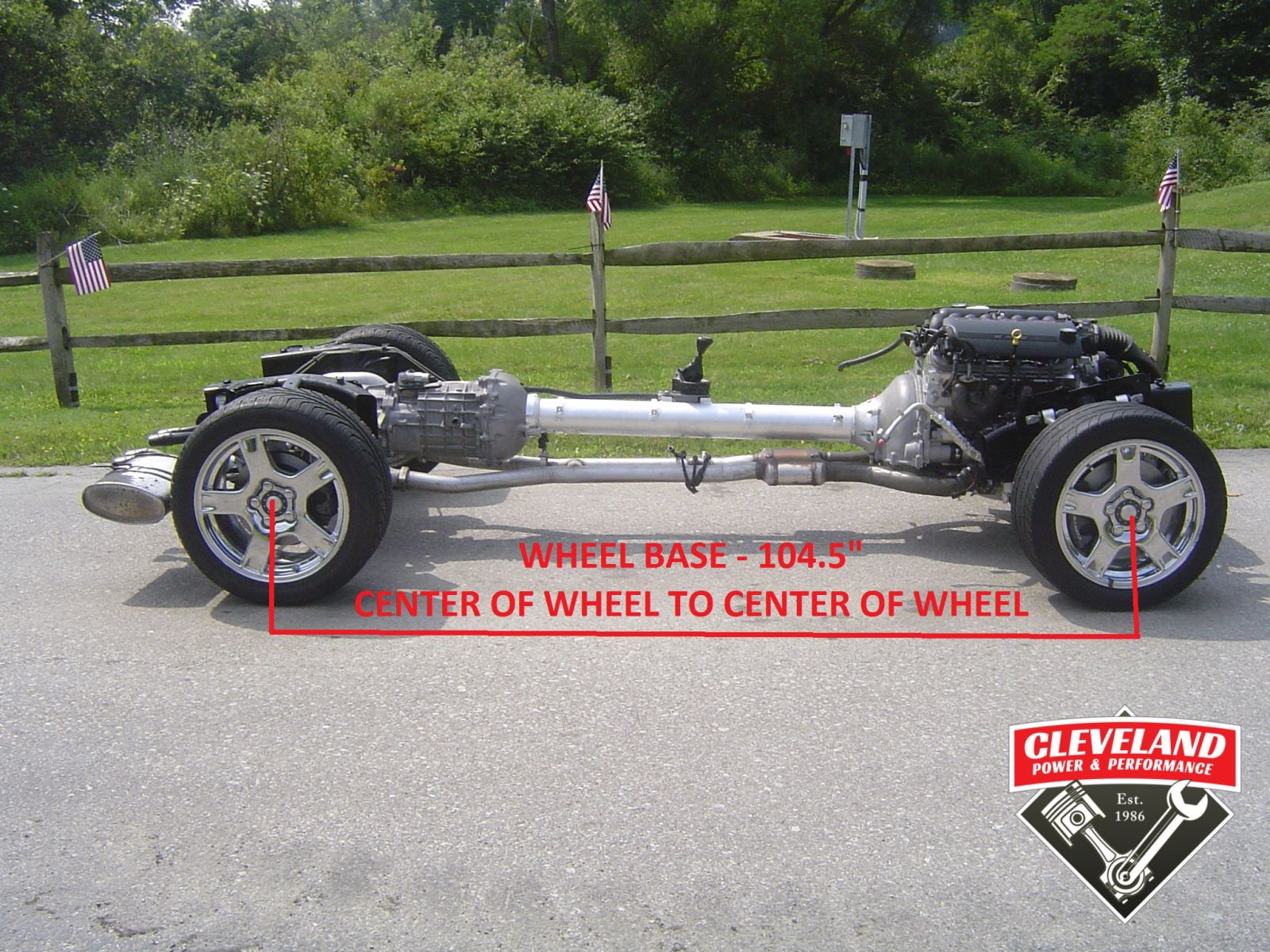
Pics for inspiration:
After breaking multiple drivetrain pieces I fully committed to the swap! Turns out it dropped a good bit of weight as my car is now 2400lbs with twin turbos, but still need to add a cage. After some measuring I went with a 58" fab 9 inch with a spool, custom driveshaft with Sonnax yoke and 1350 joints, Jegs's 15x10's with 4.5" backspacing, Wilwood drag brakes, double adjustable shocks and a universal triangulated four link kit. Have a big anti roll bar to install as well.
I could probably go with another inch of backspace with custom beadlock wheels but these fit the bill for mockup with 28x10.50W's
Header build: Purchased 304 stainless from Stainless Headers MFG/Experimental Aircraft Exhaust INC.
One thing to note on flanges (some prolly know this) not all flanges are created equal (hell, not all stainless is created equal). When they are laser cut they are very raw. Some companies will sell them straight off the laser others will clean them up 1st. Mine where ready to install. I did have to shave a little off the bottom (around spark plugs) to give the boot protectors some room (dip stick mount also needed some attention cause the flange covered half the mounting hole). The flanges are 3/8 thick with 2" primaries. I didn't take any pics of all the stainless as is was all individually wrapped so I took a pic of a few pieces as I was using it.
I ordered a kit which included: 2 Flanges 2" round Port, 12 2" Mandrel Bent J Bends, 2 Merge Collectors (2" Primary 3" Merge 3 1/2" transitional Exit), 2 O2 sensor bungs, 4 Pack collector tabs, Purge Caps, and Tig filler rod 1/8lbs each of 0.045 and 1/16, 2 3/12" VBands
I took one of the JBends and traced it out on cardboard for a pattern. Then marked out 90* 45* 22* angles on the J. I wanted to stay as close as possible to these angles to keep it unified and somewhat symmetrical (no weird angles was my thinking). Plus the card board pattern made it easy to draw the cut line and keep the pipe at a 2" circumference. It worked for 85% of the project.
One of the reasons I went down this road is I had quotes for custom headers from $4300 - $6000 and 8-10 weeks of my car sitting in somebody else garage. Thats not me. I do 99.9% of the work on this car and I didn't have 8-10 weeks. The total bill for all the stainless was $1400. So I was either going to have a $1400 pile of cutup stainless or two headers..
Every piece was cut and ground flat on the end so there was absolutely no gap between joints. This allowed not using a filler rod 90 % of the time and fusing the pieces together with a pulse setting on the Miller. If I had a rotisserie the weld would have been prettier. But you can see where I had to stop turn the pipe and start again.
I started on the passenger side as i knew it would be the most complicated as I had to go around the starter. But I did pick the easiest hole after getting and idea of how they would all lay out and some simple mock ups. I also spot welded the 1st one. But looked for a different method as spot welding took more hands then I had. The new method was blue tape. I found that if I wrapped the blue tape tight it would hold all the pieces together (I was trying to make each leg with as few pieces as possible, 3 was my goal). I cut slits in the tape when I was ready to weld and spot welded each side (180* out) and then peeled the rest of the tape off and continued welding. Worked like a charm.
Also found that I could wrap each end and cram it in the flange and it would hold the weight..
Passenger side mock complete
The only thing I had to worry about on the driver side was clearing the steering shaft. But it was just a complicated as the passenger.
Passenger side
Well I thought I had the passenger and driver side ... but this looks like the passenger again..
Yeah baby ... your underside looks so sexy and pretty..
All taped and and final mockup. Believe it or not, they are not the lowest part of the car... My initial thought had them coming out in front of the wheels. But when I laid some Jbends in place it was just too much stainless and would generate too much heat in the bay for me.
Here is a pic of the merge collectors. The headers is the 1 7/8 Kooks I was running vs the new race collector...
Polishing them up on a bench grinder with a fine wire wheel, individually before final Assembly. I could have mirror finished them but I just wanted to matte them cause I knew they would turn after a few runs.. besides I hate polishing ...
More polishing lots of polishing....
I'll post up more on making the exhaust pipes.
Here is your weak link,
Hence sides of the toque tube channel on the chassis to prevent motor and trans spin torque.
So on the OEM, its the front and rear cradles that are preventing the twisting as well as the torque tube as well.
Drive line self supported from twisting on it own, via the torque tube.
In your case, sold motor mounts will support the motor from twisting on the front cradle, but where you are supporting the rear of the trans to the chassis (and cut parts out), the front to rear of drive line area on the chassic is thin metal plus add no torque tube to prevent frame twisting from the drive line as well.
So frame front to back since you now using it for drive line twist torque support, need to be beefed up , so your not twisting the frame like a wet noodle on launches isntead.
Note, B pillar area is just one huge crumple zone, with no real twist suport in this area. So with the way you have the back end suported, if of if it will be the first that twists, up at the crumple zone at the front of the torque tube areas of just in between the two where you have the back of trans suported isntead. The dead give away if the latter, will be when the light weight floor panels end up with huge heaves/rippes in them.
Hence reminds me of the old hot rods that you cut the hell out of the frame to lighten it to try to make the car faster, only to find that lighten frame twisted like a pretzel/snapped in half when you throw any HP at launch at it instead.
So on that note, will find that C6 solid rear end drag cars have one thing in common, and the C6 frame is not used, but an new framed welded up for use (with roll cage as well), that does have drive line twist support when the torque tube is not in play.
First that isnt a picture of my trans mount, just used as a reference for what I've found that others have done. I agree and wanted more support there, so mine has .125 thick angle steel and 1x2 inch .120 tubing reinforcing it. I also have 1 5/8" .120 tubing between the frame rails as well to support it where the subframe was. Yet another 1.5" square .125 bar goes across the frame rails to support the anti roll bar mounts.
I dont know anyone that would build a car for drag racing and not do a roll cage, so the car will be supported in all directions. Anyone that cuts into the frame for lightness isnt very bright in my opinion, much better ways to lose weight in a vehicle. Personally I dont think the small part of the tunnel that was trimmed will give up much strength, nor did the flimsy aluminum tunnel brace do much to solidify the car. But even if it did the main roll cage hoop supports go down to .125 plates on the tunnel, under which is another 1 5/8" .120 wall tubular driveshaft loop as well as another 1 5/8" bar supporting the 4 link brackets. The rear roll cage supports also go down directly to the rear frame rails so there isn't much twisting able to be done and every junction of tubing and tubing to frame is gusseted so overall the car should be much stiffer than stock.
Corvette is a sports car; thus the irs for better handling. Why not just buy a solid axle Camaro if you want a drag race car. It will be a whole lot cheaper and easier. Of course, it's your car and you decide what to do with it. Good luck if you decide to do it.
Corvette is a sports car; thus the irs for better handling. Why not just buy a solid axle Camaro if you want a drag race car. It will be a whole lot cheaper and easier. Of course, it's your car and you decide what to do with it. Good luck if you decide to do it.
That would be easier, but not nearly as fun (to me at least). Thanks, yes decision has already been made, trans is mounted to engine, driveshaft, axle, coilovers, fuel cell, etc are already in the car and its down to 2,331 lbs before the cage is finished so perhaps this "sports car" turns out to be a good bit lighter than the typical solid axle drag car.
Glad I found this. I plan to do the same thing. Looking to pick up a base model soon.
Took a break from the car for a few weeks but back at it again and its turning out well. Wasn't really a goal from the beginning, but I was able to make this all reversible if for some reason I wanted to go back to a stock style suspension for some reason (no idea why I would). Ended up being able to use the stock upper shock mounts for the dual adjustable coilovers. Got the 4 link mounts and arms mocked up, then cycled the suspension for first time last night and everything seems smooth. Hopefully get most of the finish welding done on the suspension this week so I can put it back on the ground and start on the cage. I got the Rhodes C5 10 point cage kit and from what I test fit so far it tucks nicely into the C6.
Took a break from the car for a few weeks but back at it again and its turning out well. Wasn't really a goal from the beginning, but I was able to make this all reversible if for some reason I wanted to go back to a stock style suspension for some reason (no idea why I would). Ended up being able to use the stock upper shock mounts for the dual adjustable coilovers. Got the 4 link mounts and arms mocked up, then cycled the suspension for first time last night and everything seems smooth. Hopefully get most of the finish welding done on the suspension this week so I can put it back on the ground and start on the cage. I got the Rhodes C5 10 point cage kit and from what I test fit so far it tucks nicely into the C6.
So far so good, she looks like a barn find after two months in the garage. I finished welding the cage and painted it, got the 4 link/9" brackets wrapped up, coilovers mounted and sat her down on the scales, she tipped them at 2445lbs! Have a few little things to add but it looks like the 2500lb goal is a reality.
So far so good, she looks like a barn find after two months in the garage. I finished welding the cage and painted it, got the 4 link/9" brackets wrapped up, coilovers mounted and sat her down on the scales, she tipped them at 2445lbs! Have a few little things to add but it looks like the 2500lb goal is a reality.
That weight is nuts. Do you still have things you can take out or is that all in?
That weight is nuts. Do you still have things you can take out or is that all in?
I could certainly make it lighter if I tried. Stereo/speakers are still in it, power windows and all stock glass, don't have a carbon hatch or anything, I used an iron instead of aluminum 9" carrier, I did a mild steel cage which added more weight than chromoly but it was way less hassle to install and cheaper. It has Jegs (vision) wheels on it that aren't the lightest things, heck it still has mufflers on it. So if I really tried I could make it a good bit lighter but I still like to cruise around in it.
Just picked up a base roller. I think I am wanting to go with a 8.8 instead of a 9in. Cost/weight? Don't think I will be doing a stick shift this time around. A nicely built powerglide should make this thing boogey.
Just picked up a base roller. I think I am wanting to go with a 8.8 instead of a 9in. Cost/weight? Don't think I will be doing a stick shift this time around. A nicely built powerglide should make this thing boogey.
I thought about the 8.8 but its a bit harder to change gears, not much weight difference (~20lbs with a spool), depending on what version don't have to fiddle with deleting C clips or upper mounts being in wrong place. A bare 9" wasnt pricey and came in at 240lbs complete end to end with lugs, wheels, tires, brakes, 3.70 gear, axles, spool, yoke, and four link brackets.
Built manual boxes are almost impossible to get right now, so I did exactly that, slapped a glide with a big stall and a precision shifter in it. Tracks are still a little weird around here, so at this point I just want to do wheelies on my street
Ah, I thought it was a bigger difference in weight. I'll be honest, that's new territory for me. Moser sells built 8.8s and you can get them with no mounts/brackets. Comes in around $3000 with a spool, brakes, c clip eliminators, 35 spline axles, beefy studs, billet yoke, custom length/pinion offset, and your choice of gear.