When you click on links to various merchants on this site and make a purchase, this can result in this site earning a commission. Affiliate programs and affiliations include, but are not limited to, the eBay Partner Network.
I added this information to DPG's BIG THREE post and also added it to my IMPORTANT ELECTRICAL INFORMATION (Long!) sticky post. It seemed like some more information to post here to arm C5 owners with more electrical ammo.
If your having power / voltage issues,, here are some ways that you can use to help combat the issue:
I've been thinking about making this post for a while. Its raining and cold out and my ZO6 is beyond dead so, I'm bummed out.
If you improve the following MAJOR wiring paths, you will significantly improve the electrical system operation and efficiency!! Ive been studying this issue for a LONG TIME and here are my recommendation:
1- Follow this post and clean and tune up your IGNITION SWITCH. Its FREE and works very well!! Over a period of time the contacts inside the switch get burnt and some critical body control and PCM circuits receive less than actual battery voltage. Once you clean the ignition switch and improve the contact pressure on the switches, you will see a significant improvement in module functionality:
2- Improve the battery to alternator circuit. The alternator charges the battery thru the starter solenoid. In that circuit there are in line fuseaible links and eyelet type connections that are exposed to heat, weather and corrosion. As time goes by, these connections become POOR and alternator performance suffers. Examine the attached GM Schematic and notice how the alternator connects to the battery and the fusible links on the starter solenoid for the alternator.
-----------------------------------------------------------------
Recommendation! Run a 4 - 8 gage wire from the POSITIVE battery terminal to the field terminal on the back of the alternator. Obtain a 60 amp fuse and fuse holder and install a fuse in that line near the battery to protect that hot wire from short circuits.
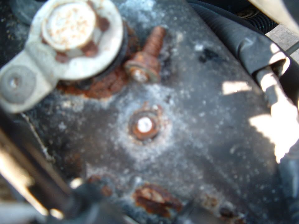
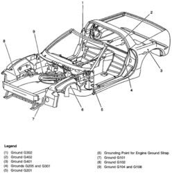
3- Better Chassis Ground at G-104/108. Chassis ground G-104/108 is a significant grounding point for numerous other chassis grounded circuits. ALL of the other chassis ground points enter the negative battery terminal through this wire.
Remove the negative battery terminal and remove the plastic/rubber cover from the battery terminal. You will see that the wire connections to the neg terminal are CRIMPED to the wire. This crimped connection frequently gets corroded/burnt/loose etc.. and causes poor performance. Remove the small negative ground wire from that connection and replace it with a 4 -8 gage wire. When you get the wire in the crimp connection, solder the connection. I use a giant soldering gun or a torch on low flame. Use lots of non acid flux for a good clean solder joint.
While your examining the battery terminals, inspect the POSITIVE BATTERY terminal wire crimped connections for proper conditions.
MAKE SURE THAT YOU PROPERLY ATTACH THE BATTERY TERMINALS TO THE BATTERY!! They need to be clean and tight. The GM torque spec for 97-2003 battery terminals is 11 ft/lbs.
If you follow the POSITIVE battery wires out of the crimped connection on the battery lead, you will see that it goes to TWO places:
- The Starter (main starter wire)
- The Engine Compartment Fuse Block, B+ terminal (main power for ALL the under-hood loads)
If you look at the pic below, you will see that the under hood fuse center has a B+ terminal on it that is where the battery cable connects to power the fuse block. You will also notice that theres a SECOND wire on that terminal. That wire is the B+ power wire for the Instrument Panel Fuse Block. NOTE! You will also note that in my pic, theres a "THIRD" connection. Thats my heated seat power line. You will NOT have this wire on yours
Some people have improved instrument panel circuit operation by incorporating that feed wire directly to the battery terminal; either in the crimp connection or if you have a side and top terminal on your battery, on one of those terminals.
General Chassis Grounds and circuit performance. Over the years, I have seen too many electrical problems to count. Many problems that I have seen can be contributed to poor chassis grounds. I have covered this in many electrical post but, make sure that you inspect and maintain your chassis grounds. Heres are some well documented examples of what hiding at your ground and grounding points!
THE GROUND SCHEMATIC!
The BIG THREE really does help. Get that engine and alternator better grounded to the CHASSIS!!!!
I hope this helps the BIG THREE get some more exposure and to help those of you who are experiencing POWER issue solve them. I will also copy this into my sticky (IMPORTANT ELECTRICAL INFORMATION (Long)
I have a 01 convertible, and I've been having problems with electrical issues for a while now. I've pulled codes, and there has never really been anything that offers any help in resolving this stuff. I seem to have it isolated down to the wiring harnesses into the drivers door. At first, my window wouldn't go down or up, dug into the connectors between the pillar and door, jiggled things around a bit, and got it working. Cleaned connections, and everything worked fine. Months later, same thing, only now, the tire sensors would go offline, and the car would go into limp mode. Or traction control would go offline, or some other electrical issue would occur. Sometimes multiple issues simultaneously. Now,my headlights will suddenly go off and on as. I'm driving, or not come on when I switch them on. Also, a battery drain issue, which I've read about in this forum, and have checked the drain at .05, but mine seems to be in the door. The radio doesn't turn off, or the power antenna doesn't retract, or some other item which is supposed to turn off when the door is opened, doesn't sometimes. Jiggle wires, problems solved. My question for someone who might know, and Mr Curlee seems to be the resident expert, is, does all or many of the circuits in the C5 go thru the drivers door harness before proceeding to their ultimate destination? Also, since it looks like my only option is to pull the dash to get to the wiring, as there is no way to work on it with just the space between the door and body with the door open, can anyone tell me how long that operation might take? I need to repair my HUD at some point (it dropped) and need to pull the dash anyway, so I'm thinking I'll do all at once, unless someone knows of another option, or fix for this electrical issue if it's a common problem. I'll save the HUD for later.
Any advice or suggestions are greatly appreciated folks.
I have a 01 convertible, and I've been having problems with electrical issues for a while now. I've pulled codes, and there has never really been anything that offers any help in resolving this stuff...
When having the problems described, pull the codes with the engine running. Check to see if you have any codes related to the Serial Bus and/or loss of communication with modules.
Originally Posted by edge 01
...I seem to have it isolated down to the wiring harnesses into the drivers door... ...The radio doesn't turn off, or the power antenna doesn't retract, or some other item which is supposed to turn off when the door is opened, doesn't sometimes. Jiggle wires, problems solved...
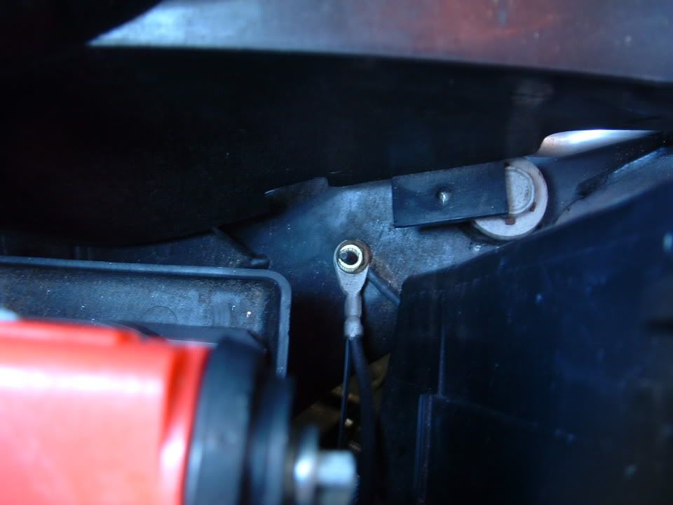
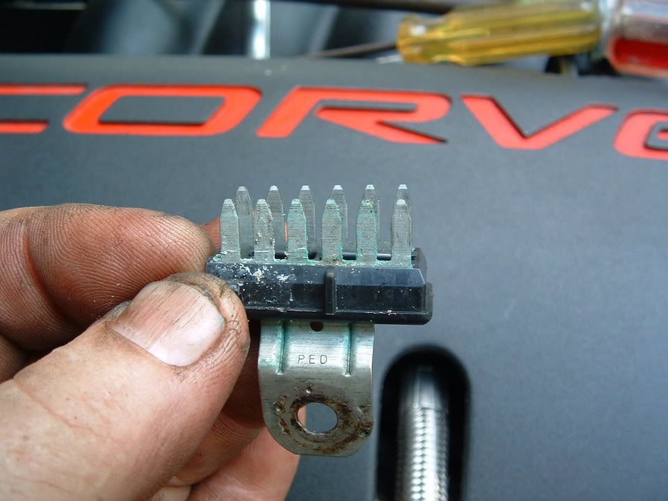
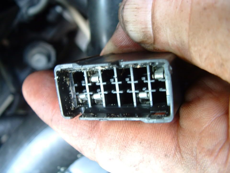
The Serial Bus goes through the rubber accordion to the door control module. The female pins of the connector on that wire harness get deformed, causing bad contacts and loss of communication/corruption in the Serial Bus. This is well documented and you can read more here.
You already know that there are bad contacts there. The solution is to fix the female pins or replace the connector. If you want to replace the connector take a look at this post for some ideas. Your radio is probably not responding because it is tied to the Serial Bus.
Originally Posted by edge 01
...does all or many of the circuits in the C5 go thru the drivers door harness before proceeding to their ultimate destination?...
It is not that they all go through it, but that once the Serial Bus is corrupted all other devices that use it get affected.
When having the problems described, pull the codes with the engine running. Check to see if you have any codes related to the Serial Bus and/or loss of communication with modules.
The Serial Bus goes through the rubber accordion to the door control module. The female pins of the connector on that wire harness get deformed, causing bad contacts and loss of communication/corruption in the Serial Bus. This is well documented and you can read more here.
You already know that there are bad contacts there. The solution is to fix the female pins or replace the connector. Your radio is probably not responding because it is tied to the Serial Bus.
It is not that they all go through it, but that once the Serial Bus is corrupted all other devices that use it get affected.
LOL!! THANK YOU! You saved me a LOT of typing! Could NOT have sed it better..
When having the problems described, pull the codes with the engine running. Check to see if you have any codes related to the Serial Bus and/or loss of communication with modules.
The Serial Bus goes through the rubber accordion to the door control module. The female pins of the connector on that wire harness get deformed, causing bad contacts and loss of communication/corruption in the Serial Bus. This is well documented and you can read more here.
You already know that there are bad contacts there. The solution is to fix the female pins or replace the connector. If you want to replace the connector take a look at this post for some ideas. Your radio is probably not responding because it is tied to the Serial Bus.
It is not that they all go through it, but that once the Serial Bus is corrupted all other devices that use it get affected.
Hey, thanks so much. I really appreciate the help.
I've rebuilt one of the connectors a few years ago, as well as the driver seat connector after the seat stopped working. Just have to pull codes, see what I have and do it again.
Are the female pins available?
I'm in the same boat, have been through the cleaning before, but got REP and all the codes a week or so ago. First time in two years, but I know what's coming.....


 so, I'm bummed out.
 They need to be clean and tight. The GM torque spec for 97-2003 battery terminals is 11 ft/lbs.
 NOTE! You will also note that in my pic, theres a "THIRD" connection. Thats my heated seat power line. You will NOT have this wire on yours


 LOL!! THANK YOU! You saved me a LOT of typing! Could NOT have sed it better..