


Elec. Question.
Thread Starter
Safety Car


Joined: Oct 2003
Posts: 3,699
Likes: 16
From: Sun City- Menifee Calif.
Hello, Would an ign. switch going bad possibly cause Codes PO117and or PO118 High & low voltage to coolant temp sensor? Been having this problem on & off for months now. Will run fine for 2-300 miles then pop up again. Both oil & coolant sensors have been replaced, Thanks, D. 

Tech Contributor


Joined: Dec 1999
Posts: 32,910
Likes: 2,402
From: Anthony TX
CI 6,7,8,9,11 Vet
St. Jude Donor '08
Hello, Would an ign. switch going bad possibly cause Codes PO117and or PO118 High & low voltage to coolant temp sensor? Been having this problem on & off for months now. Will run fine for 2-300 miles then pop up again. Both oil & coolant sensors have been replaced, Thanks, D.
The 5VDC Reff signal for those sensors comes from the PCM. If everything else is working fine, I seriously doubt it. You can measure the Reff voltage with a meter. If its correct it will read around 4.9X VDC. You can also read the Hot in RUN and Start voltage on the fuse test points supplied by ignition switch and see if you have close to battery voltage.
You need to carefully examine the harness connector for the sensor and the wiring. Make sure that the female pins in the connector are not spread apart are not damaged and the wiring is 100% intact.
Thread Starter
Safety Car
Joined: Oct 2003
Posts: 3,699
Likes: 16
From: Sun City- Menifee Calif.
The 5VDC Reff signal for those sensors comes from the PCM. If everything else is working fine, I seriously doubt it. You can measure the Reff voltage with a meter. If its correct it will read around 4.9X VDC. You can also read the Hot in RUN and Start voltage on the fuse test points supplied by ignition switch and see if you have close to battery voltage.
You need to carefully examine the harness connector for the sensor and the wiring. Make sure that the female pins in the connector are not spread apart are not damaged and the wiring is 100% intact.
You need to carefully examine the harness connector for the sensor and the wiring. Make sure that the female pins in the connector are not spread apart are not damaged and the wiring is 100% intact.

Thread Starter
Safety Car
Joined: Oct 2003
Posts: 3,699
Likes: 16
From: Sun City- Menifee Calif.
Thanks, Bill! I have replaced the pigtail for the temp sensor. The last prob I was having was the coolant temp would not come up to normal oil temp would be normal and coolant would read like 97 -110 degrees .Changed out sensor, and all was good for 2-300 miles or so. then yesterday, it all started again coolant temp pegged on hot, and engine misfiring Maybe PCM? I have done all the door connectors . And grounds look good Starter wires are good and tight. No moisture under pass. floor , Under Battery is completely dry underneath.
Tech Contributor
Joined: Dec 1999
Posts: 32,910
Likes: 2,402
From: Anthony TX
CI 6,7,8,9,11 Vet
St. Jude Donor '08
Pull out the new sensor and read it with an OHM METER. Submerge it in hot water and see if the resistance reading changes SMOOTHLY.
Compare it with the old sensor. You could just have a bad sensor.
Bill
Compare it with the old sensor. You could just have a bad sensor.
Bill
Thread Starter
Safety Car
Joined: Oct 2003
Posts: 3,699
Likes: 16
From: Sun City- Menifee Calif.
Are the oil sensor and coolant sensor connected in some way? Yesterday when the probs. were happening, The oil temp in the DIC. would read "LOW" on and off. Every time I think this is fixed, it happens again. Thanks, D.
Thread Starter
Safety Car
Joined: Oct 2003
Posts: 3,699
Likes: 16
From: Sun City- Menifee Calif.
Do you think it would be worth it to change ign. switch? I have read where bad ones can cause many strange things to happen. I am at wits end with this car.  Thanks!
Thanks!
Tech Contributor
Joined: Dec 1999
Posts: 32,910
Likes: 2,402
From: Anthony TX
CI 6,7,8,9,11 Vet
St. Jude Donor '08
If the Ref Voltage goes away, you have to figure out if its a PCM issue, grounded sensor wire somewhere, or a grounded sensor.
The Wiring harness that runs down the top of the drivers side of the engine along the head is WELL KNOWN to get damaged. Look for RUB/CHAFE damage on that entire harness. Especially where it bends down aroun the BACK of the engine.... UNTAPE it if you have to see if any of the wires are damaged.. YES, those sensor wires run inside that harness......

 .
. Somewhere to start!

Bill
Corvette Stories
The Best of Corvette for Corvette Enthusiasts

Top 10 Most Expensive Corvettes Ever Sold on Bring A Trailer
Brett Foote
10 Things Every Corvette Owner Needs (2026 Edition)
Michael S. Palmer
8 Most "Only Corvette Owners Understand" Quirks and Problems
Pouria Savadkouei
10 Reasons the C6 Z06 is Still A Performance Benchmark After 20 Years
Joe Kucinski
How Much Horsepower Every Corvette Engine "LOST" in 1972
Joe Kucinski
Top 10 DOs and DON'Ts for Protecting Your Convertible Top!
Michael S. Palmer
Top 10 Most Explosive Corvettes Ever Made: Power-to-Weight Ratio Ranked!
Joe Kucinski
150 hp to 1,250 hp: Every Corvette Generation Compared by the Specs That Matter
Joe Kucinski
8 Coolest Corvette Pace Cars (and Replicas) of All Time
Verdad Gallardo
Tech Contributor
Joined: Dec 1999
Posts: 32,910
Likes: 2,402
From: Anthony TX
CI 6,7,8,9,11 Vet
St. Jude Donor '08
I had a wire issue that blew fuses when I went FULL THROTTLE 

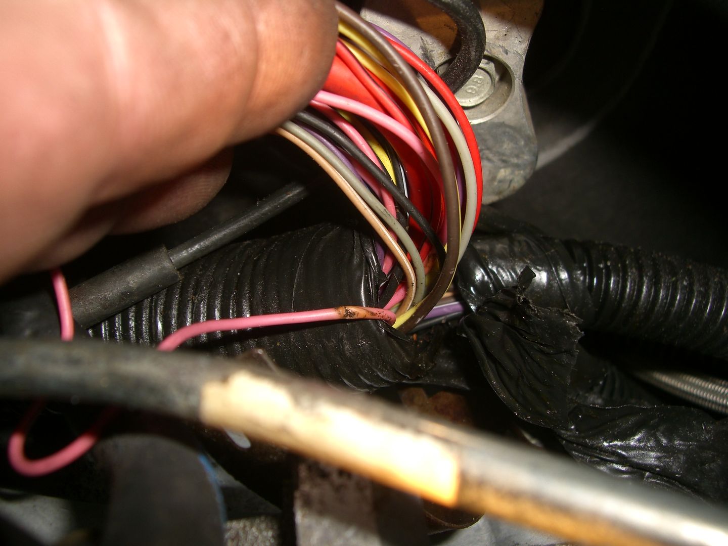
Here was the culprit: A pinched wire. Easily fixed once I opened the harness and looked for it.
The PINK wire is 12 VDC Switched power for one bank of coils.
SUCKS HARD to have to drive the car on SIX CYLINDERS when that fuse blows!!
Here was the culprit: A pinched wire. Easily fixed once I opened the harness and looked for it.
The PINK wire is 12 VDC Switched power for one bank of coils.
SUCKS HARD to have to drive the car on SIX CYLINDERS when that fuse blows!!


Thread Starter
Safety Car
Joined: Oct 2003
Posts: 3,699
Likes: 16
From: Sun City- Menifee Calif.
Thread Starter
Safety Car
Joined: Oct 2003
Posts: 3,699
Likes: 16
From: Sun City- Menifee Calif.
Tech Contributor
Joined: Dec 1999
Posts: 32,910
Likes: 2,402
From: Anthony TX
CI 6,7,8,9,11 Vet
St. Jude Donor '08
Until you stick a METER on the wire with the reff voltage and prove that the voltage either GOES AWAY when the issue happens or remains when the issue happens, NO ONE can say for sure.
Still, you have to rule out a damaged wire or connector.
SO, the answer to the question is NO, until you prove other wise.
IF,,,,,,,,,,,,, The reff voltage goes away, you would have multiple DTCs for ALL of the sensors that need 5 VDC Reff to work. Check the DTCs when the error is actually happening! When it fails just press and hold RESET until any messages in the DIC clear and then read the DTCs without turing off the ignition..
Bill
Thread Starter
Safety Car
Joined: Oct 2003
Posts: 3,699
Likes: 16
From: Sun City- Menifee Calif.
I have been online and found a way to check if sensor is bad. Says to disconnect sensor, and if temp reading goes from hi 284 F. Where it is now with the code PO117, to low -40F. The sensor is bad. And another test is to connect the wires in sensor plug and if it goes to the very high temp, the wiring is ok. My question is it ok to do that and it wont blow a fuse. ? Thanks, D.
Tech Contributor
Joined: Dec 1999
Posts: 32,910
Likes: 2,402
From: Anthony TX
CI 6,7,8,9,11 Vet
St. Jude Donor '08
QUOTE! "Pull out the new sensor and read it with an OHM METER. Submerge it in hot water and see if the resistance reading changes SMOOTHLY."
Here ya go:
https://axleaddict.com/auto-repair/C...re-Sensor-Test
How to test any Temp Sensor:
TEMP vs RESISTANCE:
-40 deg (C) = 102,122 OHMS
150 deg (C) = 48.1 Ohms
Here ya go:
https://axleaddict.com/auto-repair/C...re-Sensor-Test
How to test any Temp Sensor:
TEMP vs RESISTANCE:
-40 deg (C) = 102,122 OHMS
150 deg (C) = 48.1 Ohms
Thread Starter
Safety Car
Joined: Oct 2003
Posts: 3,699
Likes: 16
From: Sun City- Menifee Calif.
So, I unplugged the sensor connector, Turned key on Temp said approx. ambient temp 57 deg. Cleared PO117C code, started eng. Temp started rising, normally, then went to xxx. And gauge pegged. Then I connected the contacts in the plug with paper clip and did the same thing same result But threw PO118C code. I don`t understand how these things could happen with the sensor UNPLUGGED??? Maybe this will help with the diagnosis. Thanks for all the help. D.
Maybe this will help with the diagnosis. Thanks for all the help. D.
Tech Contributor
Joined: Dec 1999
Posts: 32,910
Likes: 2,402
From: Anthony TX
CI 6,7,8,9,11 Vet
St. Jude Donor '08
So, I unplugged the sensor connector, Turned key on Temp said approx. ambient temp 57 deg. Cleared PO117C code, started eng. Temp started rising, normally, then went to xxx. And gauge pegged. Then I connected the contacts in the plug with paper clip and did the same thing same result But threw PO118C code. I don`t understand how these things could happen with the sensor UNPLUGGED??? Maybe this will help with the diagnosis. Thanks for all the help. D.
Maybe this will help with the diagnosis. Thanks for all the help. D.Leaving the sensor in the block UNPLUGED does NOTHING other than prevent the coolant from spilling out...... The business end of the CTS is the harness connector. IT MUST be connected to the sensor so the 5 VDC Reff voltage can be feed through the sensor variable resistor (which change resistance vs temp) and output a represenative voltage with respect to coolant temp.
The P-0118 means that the 5 VDC Reff voltage is shorted to the PCM signal wire which is expeting to see something LESS than 5 VDC and more than 0 VDC.
Bill
Thread Starter
Safety Car
Joined: Oct 2003
Posts: 3,699
Likes: 16
From: Sun City- Menifee Calif.
The PCM is designed to operate with sensor outputs between a specific HIGH and LOW reading. When you UNPLUG the sensor or short out the harness connector with a paperclip, that causes the PCM to either see 0 OHMS or full reff voltage. Both are FAR OUTSIDE the expected sensor reading..
Leaving the sensor in the block UNPLUGED does NOTHING other than prevent the coolant from spilling out...... The business end of the CTS is the harness connector. IT MUST be connected to the sensor so the 5 VDC Reff voltage can be feed through the sensor variable resistor (which change resistance vs temp) and output a represenative voltage with respect to coolant temp.
The P-0118 means that the 5 VDC Reff voltage is shorted to the PCM signal wire which is expeting to see something LESS than 5 VDC and more than 0 VDC.
Bill
D.