


IMPORTANT ELECTRICAL INFORMATION (Long!)

Thread Starter
Tech Contributor


Joined: Dec 1999
Posts: 32,910
Likes: 2,402
From: Anthony TX
CI 6,7,8,9,11 Vet
St. Jude Donor '08
So,,,analyzing everthing that your telling me,,,,lets try this. Open BOTH doors. Find the rubber accordion tube between the door and door frame. Pop the tube out of the door and door frame (is easy) and fish out the TWO connectors fo the door wireing harnesses out the door frame.

seperate the connectors, inspect, clean and repair as necessary. Look for bare wires and seal as necessary See if that helps.
BC
seperate the connectors, inspect, clean and repair as necessary. Look for bare wires and seal as necessary See if that helps.
BC
Instructor

Joined: Mar 2007
Posts: 168
Likes: 0
From: Burlington NJ
Im having this same issue as VetteDawg, i found the first connector had a bare wire on each side (of course the one with the clear cover), i wrapped either side with electrical tape, so if that doesn't work i'll have to check the second connection. Its tight quarters working in between the doors, if the tape doesnt work can anyone recommend a better method for sealing off that wire? Perhaps some well placed silicon or something like that?
Thanks,
Alex
Thanks,
Alex
Heel & Toe
Joined: Jul 2008
Posts: 15
Likes: 0
From: York PA
thanks Bill for the suggestion. I just tried that to no avail, any other suggestions are greatly appreciated. I'm not so concerned w/ windows, but if you think that could cause it to not start after 20 mins...
Some of the error code's might have been helpful in my previous post-- P0418,C1214,B2282,b2283,b3384,b2285,b226 ,b2264,b2605,u1215.
Most of those code are "H" except P0418, C1214 are current codes.
Some of the error code's might have been helpful in my previous post-- P0418,C1214,B2282,b2283,b3384,b2285,b226 ,b2264,b2605,u1215.
Most of those code are "H" except P0418, C1214 are current codes.
Thread Starter
Tech Contributor
Joined: Dec 1999
Posts: 32,910
Likes: 2,402
From: Anthony TX
CI 6,7,8,9,11 Vet
St. Jude Donor '08
Right next to the BCM (to the left of it) are TWO skinny Grey connectors. Those are the STAR serial buss connectors. All of the modules communications combine here.
Find the one that has the least amount of wires in it. There should be four wires in the correct one. The top of the connector is actually a shorting bus. Pull the TOP of the connector off and then see if that corrects your issue.
NOTE. This will temporally disable your remote door functions (windows,locks etc) and the seat remote functions (memory movement). With that portion of the serial buss disconnected, see if that helps. Once you finish the test, reconnect the STAR connector and clear those codes that disconnection the star buss caused.
Bill
Heel & Toe
Joined: Jul 2008
Posts: 15
Likes: 0
From: York PA
still no crank after 20 mins. dis/reconnect batt and fine for another 20.
just an observation, but it appears as though the previous owner spliced into the BCM wiring, jumped some wires together (still that way) and all sorts of whackiness. i checked a few and they were soldered, then elec. taped. Since it's run for past year that i've owned it, I would assume it's correct.
just an observation, but it appears as though the previous owner spliced into the BCM wiring, jumped some wires together (still that way) and all sorts of whackiness. i checked a few and they were soldered, then elec. taped. Since it's run for past year that i've owned it, I would assume it's correct.
Thread Starter
Tech Contributor
Joined: Dec 1999
Posts: 32,910
Likes: 2,402
From: Anthony TX
CI 6,7,8,9,11 Vet
St. Jude Donor '08
still no crank after 20 mins. dis/reconnect batt and fine for another 20.
just an observation, but it appears as though the previous owner spliced into the BCM wiring, jumped some wires together (still that way) and all sorts of whackiness. i checked a few and they were soldered, then elec. taped. Since it's run for past year that i've owned it, I would assume it's correct.
just an observation, but it appears as though the previous owner spliced into the BCM wiring, jumped some wires together (still that way) and all sorts of whackiness. i checked a few and they were soldered, then elec. taped. Since it's run for past year that i've owned it, I would assume it's correct.

BC
Heel & Toe
Joined: Jul 2008
Posts: 15
Likes: 0
From: York PA
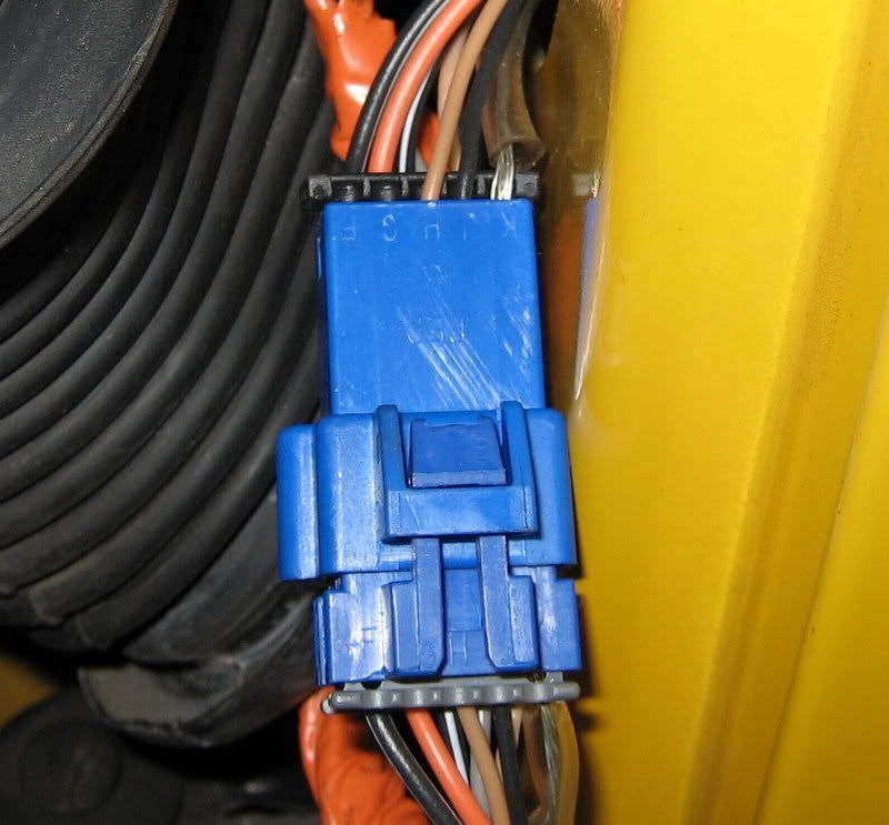
The first image is of the pink connector that mounts to the end of the BCM. The light green wire (held back by thumb) is connecting the bk/wh and gr/wh wires as well as that dark green (from under dash.)

The middle connector is in the next picture and has a red wire (from under dash) spliced into the light blue wire (sand paper is for contrast.)

Another observation, when I reconnected the BCM, interior lights lit up and car started without having to disconnect the battery (oops, I left battery connected throughout dis/reconnecting BCM, dunno if that hurts anything) 20+ mins later, no crank.
The middle connector is in the next picture and has a red wire (from under dash) spliced into the light blue wire (sand paper is for contrast.)
Another observation, when I reconnected the BCM, interior lights lit up and car started without having to disconnect the battery (oops, I left battery connected throughout dis/reconnecting BCM, dunno if that hurts anything) 20+ mins later, no crank.
Thread Starter
Tech Contributor
Joined: Dec 1999
Posts: 32,910
Likes: 2,402
From: Anthony TX
CI 6,7,8,9,11 Vet
St. Jude Donor '08
The first image is of the pink connector that mounts to the end of the BCM. The light green wire (held back by thumb) is connecting the bk/wh and gr/wh wires as well as that dark green (from under dash.)
The middle connector is in the next picture and has a red wire (from under dash) spliced into the light blue wire (sand paper is for contrast.)
Another observation, when I reconnected the BCM, interior lights lit up and car started without having to disconnect the battery (oops, I left battery connected throughout dis/reconnecting BCM, dunno if that hurts anything) 20+ mins later, no crank.
The person who BUTCHERED the BCM wires needs an *** kicking. Find out where the spliced in wires go and see if they can be removed.
Get the connections back to as close to OEM as possible and see where you stand. YES there are some BCM issue that discribe what your expierencing. Get the wires sorted out before you replace the BCM.
Corvette Stories
The Best of Corvette for Corvette Enthusiasts

Top 10 Most Expensive Corvettes Ever Sold on Bring A Trailer
Brett Foote
10 Things Every Corvette Owner Needs (2026 Edition)
Michael S. Palmer
8 Most "Only Corvette Owners Understand" Quirks and Problems
Pouria Savadkouei
10 Reasons the C6 Z06 is Still A Performance Benchmark After 20 Years
Joe Kucinski
How Much Horsepower Every Corvette Engine "LOST" in 1972
Joe Kucinski
Top 10 DOs and DON'Ts for Protecting Your Convertible Top!
Michael S. Palmer
Top 10 Most Explosive Corvettes Ever Made: Power-to-Weight Ratio Ranked!
Joe Kucinski
150 hp to 1,250 hp: Every Corvette Generation Compared by the Specs That Matter
Joe Kucinski
8 Coolest Corvette Pace Cars (and Replicas) of All Time
Verdad Gallardo

Cruising
Joined: Aug 2009
Posts: 12
Likes: 0
From: Fallbrook California
Read with interest EVERY post on here about the vast electrical issues with our cars yet never ran across anyone having the high voltage issue I do.Displays Traction control,anti-lock,air bag,high voltage, headlights flicker. Been thru the grounds, door jamb repairs as noted so well by Bill here on this forum. Sent car to "stealership" for help and was told it needed an alternator for $800.00. Ran like hell and paid the $128.00 diagnostic fee to get my car back. Changed the alt to no avail.Thinking the ign switch might be the issue as the bcm(or whatever tells alt how much to charge) is seeing a lower voltage than the alt is really putting out. Had a Suburban overcharge one time and the voltage signal to regulator was way lower than the battery voltage. Any ideas? Car is a 2004 roadster with no mods at all! Thanks. New member Mike Hayden
Thread Starter
Tech Contributor
Joined: Dec 1999
Posts: 32,910
Likes: 2,402
From: Anthony TX
CI 6,7,8,9,11 Vet
St. Jude Donor '08
Mike
Do you have an DTCs associated with the high voltage warning???
With the engine running:
Get a digital volt meter and read the battery voltage directly on the battery terminals. Note that reading.
What reading do you note on the Dash Volt meter and DIC digital voltage reading Note those readings.
Then read the terminal on the back of the alternator (BATT Terminal) under the rubber boot to ground. Note that reading.
The two reading should be very close to each other. The goal is for the readings to be the same. Then read the positive battery terminal to the alternator BATT Terminal. Note that reading.
The reading from the positive battery terminal to the alternator BATT Terminal should be ZERO or very close to it. The wire from the BATT terminal goes to the starter solenoid and from there it goes to the battery terminal. If that reading is high, you have a BAD connection between the the positive battery terminal and the alternator BATT Terminal

Next. Pin D (small red wire) in the plug on the alternator also goes to the starter. Read that voltage to ground. It also should read battery voltage. If there are major differences between these test points,, there are bad /compromised connections in that wiring run (most likely at the starter solenoid.
If the Pin D (small red wire) reads low, it could cause the alternator to output a higher than normal voltage.
Please post the readings that you get.
BC
Do you have an DTCs associated with the high voltage warning???
With the engine running:
Get a digital volt meter and read the battery voltage directly on the battery terminals. Note that reading.
What reading do you note on the Dash Volt meter and DIC digital voltage reading Note those readings.
Then read the terminal on the back of the alternator (BATT Terminal) under the rubber boot to ground. Note that reading.
The two reading should be very close to each other. The goal is for the readings to be the same. Then read the positive battery terminal to the alternator BATT Terminal. Note that reading.
The reading from the positive battery terminal to the alternator BATT Terminal should be ZERO or very close to it. The wire from the BATT terminal goes to the starter solenoid and from there it goes to the battery terminal. If that reading is high, you have a BAD connection between the the positive battery terminal and the alternator BATT Terminal
Next. Pin D (small red wire) in the plug on the alternator also goes to the starter. Read that voltage to ground. It also should read battery voltage. If there are major differences between these test points,, there are bad /compromised connections in that wiring run (most likely at the starter solenoid.
If the Pin D (small red wire) reads low, it could cause the alternator to output a higher than normal voltage.
Please post the readings that you get.
BC
Cruising
Joined: Aug 2009
Posts: 12
Likes: 0
From: Fallbrook California
Checked for codes with a Snap-on scanner and got no codes in engine section and only a high voltage code in the abs section. Voltage reads normal till the dash goes crazy, then it bounces around between 13.0 and 18. Went for a drive yesterday(Saturday) and all was well for 5 miles or so then it went crazy, got to my destination and shut car off for 20 minutes and came back and started up and all was well again. Drove home with no issues. (The car always drives well when this happens, no power loss or miss or anything).I do not have access to anything but the Snap-on scanner with OBD 2 generic setting because the cartridge only goes up to 2001. Will check voltages as instructed later today and report. I did look at the starter wiring during my inspection and noticed the wiring at pos post was tight but the whole post could be wiggled a little. No other issues. I can draw the battery down with a load tester and get 100 amps plus output from the alt with no heat at that connection so ruled out any problem there. I have a full shop at my house with 3 racks and good test equipment. I will report back. Thanks for your help here. And another question I have is I want to know what tells the alt how much to charge? Seems the alt is controlled by one of the computers and not internally like the alts I put on the rods I build. If so is the voltage adjustable somehow? Mike 949-690-4995
Melting Slicks


Joined: May 2000
Posts: 2,498
Likes: 4
From: Brentwood TN
Have you pulled the battery and checked the wiring beneath it for damage? Battery acid leaks are sometimes a problem and while this is a long shot, it's worth taking a look because the loose terminal needs to be addressed anyway.
Charlie
Charlie
Thread Starter
Tech Contributor
Joined: Dec 1999
Posts: 32,910
Likes: 2,402
From: Anthony TX
CI 6,7,8,9,11 Vet
St. Jude Donor '08
Do you realize that you can pull and read the codes without a scanner??
READING YOUR Engine Diagnostic Codes (DTCs)
The Diagnostic Display Mode is entered with the following procedure:
1) Turn on the ignition but don't start the engine.
2) Press the RESET button to turn off any warning messages. (i.e. door open, trunk open etc�)
3) Press and hold OPTIONS
4) While holding OPTIONS, press FUEL four times within a 10-second period.
Initially, on-board diagnostics go into an Automatic Mode which shows diagnostic codes in a pre-set sequence: PCM - TCS - RTD - BCM - IPC - RADIO - HVAC - LDCM - RDCM - SCM - RFA. All codes will be displayed for each. ( i.e. PCM = 4 codes)
If none are present in a given module, you will see No More Codes on the display.
There are two kinds of diagnostic codes, Current and History designated with a letter suffix, C or ;H. A current code indicates a malfunction is present in the module displaying data. A history code indicates a problem existed sometime in the last 40 or 50 ignition cycles. When not accompanied by a current code of the same number, it's potential evidence of a previous problem, now resolved, that was not removed by clearing the codes.
More likely it's an indication of an intermittent malfunction.
Intermittent codes are the most challenging of the diagnostics. An intermittent code may have happened once, may have happened more than once but is inconsistent or may be happening on a regular basis but not at the time the codes are displayed. History codes can also be caused by a current malfunction in a system that is not operating at the time codes are displayed. An example is the rear window defogger which doesn't operate until the Body Control Module detects engine rpm. For history codes set by a module that does not operate with the key on and engine off, a special diagnostic tool called a Scan Tester is necessary to properly diagnose the malfunction.
Once the system has displayed all modules, it goes into the manual mode which allows selection of each module using combinations of Driver Information Center buttons. Manual mode can also be entered during the automatic sequence by pressing any button except E/M. Once the display shows Manual Diagnostics, select a module by pressing the OPTIONS button to go forward or the TRIP button to go back. Once a module is selected, a code is displayed, and if more than one are present;
press GAGES to go forward or FUEL to go back.
To exit the diagnostic mode at any time, press E/M. If you want to erase codes in a given module, press RESET
To reset the codes once in manual mode, press and hold RESET until it displays NO CODES Press OPTIONS to go to the next module. Repeat the steps until you have reset the codes in all the computer modules.
NOTE!! Only reset the codes IF you want to - it is NOT necessary to do this. Clearing a code does not repair a problem. You are simply erasing the evidence of it in the module's memory. If you clear the code/s, and extinguish the Check Engine Light, your emissions status ready will NOT allow you to pass an emissions test until you have completed the required driving cycles.
Once you have the codes, the next question is: What to do with the information?
First, consult the factory service manual. Any serious C5 Do-It-Yourself owner should invest in the Corvette Service Manual of the appropriate model year. The Service Manual is really a requirement if you want to understand and work on your C5.
Here is very good site of DTC definitions:
http://www.gearchatter.com
Make sure to include the H or C suffix!!

Le Mans Master


Joined: Dec 2006
Posts: 7,251
Likes: 16
From: Phoenix Arizona
Do you realize that you can pull and read the codes without a scanner??
READING YOUR Engine Diagnostic Codes (DTCs)
The Diagnostic Display Mode is entered with the following procedure:
1) Turn on the ignition but don't start the engine.
2) Press the RESET button to turn off any warning messages. (i.e. door open, trunk open etc�)
3) Press and hold OPTIONS
4) While holding OPTIONS, press FUEL four times within a 10-second period.
Initially, on-board diagnostics go into an Automatic Mode which shows diagnostic codes in a pre-set sequence: PCM - TCS - RTD - BCM - IPC - RADIO - HVAC - LDCM - RDCM - SCM - RFA. All codes will be displayed for each. ( i.e. PCM = 4 codes)
If none are present in a given module, you will see No More Codes on the display.
There are two kinds of diagnostic codes, Current and History designated with a letter suffix, C or ;H. A current code indicates a malfunction is present in the module displaying data. A history code indicates a problem existed sometime in the last 40 or 50 ignition cycles. When not accompanied by a current code of the same number, it's potential evidence of a previous problem, now resolved, that was not removed by clearing the codes.
More likely it's an indication of an intermittent malfunction.
Intermittent codes are the most challenging of the diagnostics. An intermittent code may have happened once, may have happened more than once but is inconsistent or may be happening on a regular basis but not at the time the codes are displayed. History codes can also be caused by a current malfunction in a system that is not operating at the time codes are displayed. An example is the rear window defogger which doesn't operate until the Body Control Module detects engine rpm. For history codes set by a module that does not operate with the key on and engine off, a special diagnostic tool called a Scan Tester is necessary to properly diagnose the malfunction.
Once the system has displayed all modules, it goes into the manual mode which allows selection of each module using combinations of Driver Information Center buttons. Manual mode can also be entered during the automatic sequence by pressing any button except E/M. Once the display shows Manual Diagnostics, select a module by pressing the OPTIONS button to go forward or the TRIP button to go back. Once a module is selected, a code is displayed, and if more than one are present;
press GAGES to go forward or FUEL to go back.
To exit the diagnostic mode at any time, press E/M. If you want to erase codes in a given module, press RESET
To reset the codes once in manual mode, press and hold RESET until it displays NO CODES Press OPTIONS to go to the next module. Repeat the steps until you have reset the codes in all the computer modules.
NOTE!! Only reset the codes IF you want to - it is NOT necessary to do this. Clearing a code does not repair a problem. You are simply erasing the evidence of it in the module's memory. If you clear the code/s, and extinguish the Check Engine Light, your emissions status ready will NOT allow you to pass an emissions test until you have completed the required driving cycles.
Once you have the codes, the next question is: What to do with the information?
First, consult the factory service manual. Any serious C5 Do-It-Yourself owner should invest in the Corvette Service Manual of the appropriate model year. The Service Manual is really a requirement if you want to understand and work on your C5.
Here is very good site of DTC definitions:
http://www.gearchatter.com
Make sure to include the H or C suffix!!
READING YOUR Engine Diagnostic Codes (DTCs)
The Diagnostic Display Mode is entered with the following procedure:
1) Turn on the ignition but don't start the engine.
2) Press the RESET button to turn off any warning messages. (i.e. door open, trunk open etc�)
3) Press and hold OPTIONS
4) While holding OPTIONS, press FUEL four times within a 10-second period.
Initially, on-board diagnostics go into an Automatic Mode which shows diagnostic codes in a pre-set sequence: PCM - TCS - RTD - BCM - IPC - RADIO - HVAC - LDCM - RDCM - SCM - RFA. All codes will be displayed for each. ( i.e. PCM = 4 codes)
If none are present in a given module, you will see No More Codes on the display.
There are two kinds of diagnostic codes, Current and History designated with a letter suffix, C or ;H. A current code indicates a malfunction is present in the module displaying data. A history code indicates a problem existed sometime in the last 40 or 50 ignition cycles. When not accompanied by a current code of the same number, it's potential evidence of a previous problem, now resolved, that was not removed by clearing the codes.
More likely it's an indication of an intermittent malfunction.
Intermittent codes are the most challenging of the diagnostics. An intermittent code may have happened once, may have happened more than once but is inconsistent or may be happening on a regular basis but not at the time the codes are displayed. History codes can also be caused by a current malfunction in a system that is not operating at the time codes are displayed. An example is the rear window defogger which doesn't operate until the Body Control Module detects engine rpm. For history codes set by a module that does not operate with the key on and engine off, a special diagnostic tool called a Scan Tester is necessary to properly diagnose the malfunction.
Once the system has displayed all modules, it goes into the manual mode which allows selection of each module using combinations of Driver Information Center buttons. Manual mode can also be entered during the automatic sequence by pressing any button except E/M. Once the display shows Manual Diagnostics, select a module by pressing the OPTIONS button to go forward or the TRIP button to go back. Once a module is selected, a code is displayed, and if more than one are present;
press GAGES to go forward or FUEL to go back.
To exit the diagnostic mode at any time, press E/M. If you want to erase codes in a given module, press RESET
To reset the codes once in manual mode, press and hold RESET until it displays NO CODES Press OPTIONS to go to the next module. Repeat the steps until you have reset the codes in all the computer modules.
NOTE!! Only reset the codes IF you want to - it is NOT necessary to do this. Clearing a code does not repair a problem. You are simply erasing the evidence of it in the module's memory. If you clear the code/s, and extinguish the Check Engine Light, your emissions status ready will NOT allow you to pass an emissions test until you have completed the required driving cycles.
Once you have the codes, the next question is: What to do with the information?
First, consult the factory service manual. Any serious C5 Do-It-Yourself owner should invest in the Corvette Service Manual of the appropriate model year. The Service Manual is really a requirement if you want to understand and work on your C5.
Here is very good site of DTC definitions:
http://www.gearchatter.com
Make sure to include the H or C suffix!!
 too the words right outa my mouth!
  of course i learned them from you!
Bill is the Main Man!

G/L
Cruising
Joined: Aug 2009
Posts: 12
Likes: 0
From: Fallbrook California
Man...why do I feel so stupid? This is killing me! Just for sh**s and giggles I pulled the DTS'S from my wifes 2001 convert (operates perfectly)as instructed and got a long list. Cleared them and went to the gearchatter site and none of the numbers were there. My codes were like "B0516H" and all thier codes were "P" prefixed. Checked the other years and didn't find any with the "B" prefix. Will head down to the shop after work and pull DTS's from the 2004. Do I need to get the manual to get the DTS descriptions? Will one manual cover both 2001 and 2004? Mike
Thread Starter
Tech Contributor
Joined: Dec 1999
Posts: 32,910
Likes: 2,402
From: Anthony TX
CI 6,7,8,9,11 Vet
St. Jude Donor '08
There can be a number of reasons why a c5 will set a DTC. If there history, clear them and monitor. If they continue to come back,,,investigate.
You want DTCs,,,,,,you got DTCs.
DTC B0016 RF Deployment Loop Resistance Low DTC B2723 PASS-Key Detection Circuit
DTC B0017 RF Deployment Loop Open DTC B2735 PASS-Key Programming Mode Active
DTC B0018 RF Deployment Loop Short to Ground/Voltage Out of Range DTC B2795 Suspension Control Select Switch Circuit Malf
DTC B0022 LF Deployment Loop Resistance Low DTC B2852 Telescop Column In Switch Shorted to Ground
DTC B0024 LF Deployment Loop Short to Ground/Voltage Out of Range DTC B2857 Telescop Column Out Switch Shorted to Ground
DTC B0026 LF Deployment Loop Open DTC B2860 Telescoping Column Position Sensor Failure
DTC B0051 Deployment Commanded DTC B3109 Keyless Entry Transmitter Low Battery
DTC B0053 Deployment Commanded with Loop Malfunctions Present DTC B3577 Suspension Control Select Switch Contact Malf
DTC B0090 Active Switch Voltage Out of Range DTC C0550 ECU Malfunction
DTC B0091 Active Switch: Wrong State DTC C0563 Calibration ROM Checksum Error
DTC B0432 Rear Defogger Relay Circuit DTC C0615, C0620, C0625 or C0630 Suspension Position Sensor Circuit
DTC B0433 Rear Defogger Relay Circuit DTC C0665 Chassis Pitch Signal Circuit
DTC B0502 RH DRL Relay Circuit DTC C0690 Damper Control Relay Circuit Malfunction
DTC B0503 RH DRL Relay Circuit DTC C0691 Damper Control Relay Circuit Range
DTC B0507 LH DRL Relay Circuit DTC C0693 Damper Control Relay Circuit High
DTC B0508 LH DRL Relay Circuit DTC C0695 Position Sensor Overcurrent (8 volt supply)
DTC B0516 Speedometer Signal Circuit Malfunction DTC C0710 Steering Position Signal Malfunction
DTC B0521 Tachometer Signal Circuit Malfunction DTC C0750, C0755, C0760, or C0765 Tire Pressure Sensor Circuit
DTC B0605 BCM Internal Memory Malfunction DTC C1214 Solenoid Valve Relay Contact or Coil Circuit Open
DTC B0846 Battery 2 Out of Range DTC C1217 Pump Motor Relay Contact Circuit Open
DTC B0846 or B0851 Battery Out of Range DTC C1218 Pump Motor Circ Shorted to Volt or Motor Ground Open
DTC B0851 Battery 1 Out of Range DTC C1221-C1235 Wheel Speed Sensor Circuit
DTC B0856 +5 Volt Reference Out of Range DTC C1236 Low System Supply Voltage
DTC B1000 ECU Malfunction DTC C1237 High System Supply Voltage
DTC B1001 Option Configuration Error DTC C1241 MAGNA STEER Circuit Malfunction
DTC B1512-B1537 Driver Information Center (DIC) Switch Circuit DTC C1242 or C1243 Pump Motor Circuit
DTC B1542 Oil Temperature Circuit Short to Ground DTC C1247 Brake Pressure Differential Switch Activated
DTC B1543 Oil Temperature Circuit Open DTC C1248 DRP Disabled
B2187, B2192, or B2197 Power Seat Switch Circuit DTC C1254 Abnormal Shutdown Detected
DTC B2187, B2192, or B2197 Power Seat Switch Circuit DTC C1255 or C1256 ECU Malfunction
DTC B2202-B2208 Window Switch Circuit DTC C1261-C1274 EBCM Internal Solenoid Circuit
DTC B2222-B2224 Mirror Select Switch Circuit DTC C1276, P1644, or P1689 Delivered Torque Circuit
DTC B2226-B2234 Mirror Switch Circuit DTC C1277 or P1571 Powertrain Indicated Traction Control Malfunction
DTC B2236-B2239 Door Lock Switch Circuit DTC C1278 TCS Temporarily Inhibited By PCM
DTC B2242-B2244 Memory Switch Circuit DTC C1281, C1283, or C1286 VSES Sensors Uncorrected
DTC B2252-B2253 Door Key Cylinder Circuit DTC C1282 Yaw Rate Sensor Bias Circuit Malfunction
DTC B2262-B2265 Mirror Position Sensor Signal Circuit DTC C1284 or C1285 Lateral Accelerometer Circuit
DTC B2272-B2273 Mirror Motor Control Circuit DTC C1287 or C1288 Steering Position Sensor Circuit
DTC B2274-B2275 Window Motor Control Circuit DTC C1291 Open Brake Lamp Switch Contacts During Deceleration
DTC B2276-B2277 Door Lock Control Circuit DTC C1292, C1293, or C1296 Master Cylinder Pressure Sensor Circuit
DTC B2278-B2279 Door Switch Control Circuit DTC C1294 Brake Lamp Switch Circuit Always Active
DTC B2282 Battery #1 Circuit DTC C1295 Brake Lamp Switch Circuit Open
DTC B2282-B2285 Battery Supply Voltage Circuit DTC P0101 Mass Air Flow (MAF) Sensor Performance
DTC B2283 Battery #1 Circuit DTC P0102 Mass Air Flow (MAF) Sensor Circuit Low Frequency
DTC B2284 Battery #2 Circuit DTC P0103 Mass Air Flow (MAF) Sensor Circuit High Frequency
DTC B2285 Battery #2 Circuit DTC P0106 Manifold Absolute Pressure) Sensor Performance
DTC B2286-B2287 Mirror Position Sensor Circuit DTC P0107 Manifold Absolute Pressure Sensor Circuit Low Volt
DTC B2403 Front Fog Lamp Switch Circuit DTC P0108 Manifold Absolute Pressure Sensor Circuit High Volt
DTC B2408 Rear Fog Lamp Switch Circuit DTC P0112 Intake Air Temp Sensor Circuit Low Voltage
DTC B2482 Backup Lamp Relay Circuit DTC P0113 Intake Air Temp Sensor Circuit High Voltage
DTC B2483 Backup Lamp Relay Circuit DTC P0117 Engine Coolant Temp (ECT) Sensor Circuit Low Voltage
DTC B2527 Horn Relay Circuit DTC P0118 Engine Coolant Temp Sensor Circuit High Voltage
DTC B2528 Horn Relay Circuit DTC P0125 Engine Coolant Temp insufficient for Closed Loop
DTC B2567 Folding Top Release Switch Circuit DTC P0128 Coolant Temp Below Thermostat Regulating Temp
DTC B2573 Hatch Release Switch Circuit DTC P0131 or P0151 HO2S Circuit Low Voltage
DTC B2578 Right Front Turn Signal Monitor Circuit DTC P0132 or P0152 HO2S Circuit High Voltage
DTC B2583 Left Front Turn Signal Monitor Circuit DTC P0133 or P0153 HO2S Slow Response
DTC B2587 Column Lock/Unlock Drive A DTC P0134 or P0154 HO2S Circuit Insufficient Activity
DTC B2588 Column Lock/Unlock Drive A DTC P0135, P0141, P0155, or P0161 HO2S Heater Performance
DTC B2592 Column Lock/Unlock Drive B DTC P0137 or P0157 HO2S Circuit Low Voltage
DTC B2593 Column Lock/Unlock Drive B DTC P0138 or P0158 HO2S Circuit High Voltage
DTC B2597 Traction Control System Switch Circuit DTC P0140 or P0160 HO2S Circuit Insufficient Activity
DTC B2600 Seat Motor to Battery Voltage DTC P0171 or P0174 Fuel Trim System Lean
DTC B2605-B2607 Seat Position Sensor Circuit DTC P0172 or P0175 Fuel Trim System Rich
DTC B2647 Ambient Light Sensor Circuit Low DTC P0200 Injector Control Circuit
DTC B2648 Ambient Light Sensor Circuit High DTC P0218 Transmission Fluid Overtemperature
DTC B2721 PASS-Key Detection Circuit DTC P0230 Fuel Pump Relay Control Circuit
DTC B2722 PASS-Key Detection Circuit DTC P0300 Engine Misfire Detected
DTC P0325 Knock Sensor Module Performance DTC P1134 or P1154 HO2S Transition Time Ratio
DTC P0335 Crankshaft Position (CKP) Sensor Circuit DTC P1220 Throttle Position (TP) Sensor 2 Circuit
DTC P0336 Crankshaft Position (CKP) Sensor Performance DTC P1221 Throttle Position (TP) Sensor 1- 2 Correlation
DTC P0341 Camshaft Position (CMP) Sensor Performance DTC P1258 Engine Coolant Overtemperature - Protection Mode Active
DTC P0342 Camshaft Position (CMP) Sensor Circuit Low Voltage DTC P1275 Accelerator Pedal Position (APP) Sensor 1 Circuit
DTC P0343 Camshaft Position (CMP) Sensor Circuit High Voltage DTC P1276 Accelerator Pedal Position (APP) Sensor 1 Performance
DTC P0351-P0358 Ignition Coil Control Circuit DTC P1280 Accelerator Pedal Position (APP) Sensor 2 Circuit
DTC P0410 Secondary Air Injection (AIR) System DTC P1281 Accelerator Pedal Position (APP) Sensor 2 Performance
DTC P0418 Secondary Air Injection (AIR) Pump Relay Control Circuit DTC P1285 Accelerator Pedal Position (APP) Sensor 3 Circuit
DTC P0420 or P0430 Catalyst System Low Efficiency DTC P1286 Accelerator Pedal Position (APP) Sensor 3 Performance
DTC P0440 Evaporative Emission (EVAP) System DTC P1336 Crankshaft Position (CKP) System Variation Not Learned
DTC P0442 Evaporative Emission System Small Leak Detected DTC P1380 Misfire Detected - Rough Road Data Not Available
DTC P0443 Evaporative Emission Purge Solenoid Control Circuit DTC P1381 Misfire Detected - No Comm with Brake Control Module
DTC P0446 Evaporative Emission Vent System Performance DTC P1415 or P1416 Secondary Air Injection (AIR) System
DTC P0449 Evaporative Emission Vent Solenoid Control Circuit DTC P1431 Fuel Level Sensor 2 Performance
DTC P0452 Fuel Tank Pressure Sensor Circuit Low Voltage DTC P1432 Fuel Level Sensor 2 Circuit Low Voltage
DTC P0453 Fuel Tank Pressure Sensor Circuit High Voltage DTC P1433 Fuel Level Sensor 2 Circuit High Voltage
DTC P0461 Fuel Level Sensor Performance DTC P1441 Evaporative Emission System Flow During Non-Purge
DTC P0462 Fuel Level Sensor Circuit Low Voltage DTC P1514 Throttle Body Performance
DTC P0463 Fuel Level Sensor Circuit High Voltage DTC P1515 Control Module Throttle Actuator Position Performance
DTC P0480 Cooling Fan Relay 1 Control Circuit DTC P1516 Throttle Module Throttle Actuator Position Performance
DTC P0481 Cooling Fan Relay 2 and 3 Control Circuit DTC P1517 Throttle Module Performance
DTC P0500 Vehicle Speed Sensor (VSS) Circuit DTC P1518 Throttle Module Serial Data Circuit
DTC P0502 Vehicle Speed Sensor (VSS) Circuit Low Input DTC P1574 Stoplamp Switch Circuit
DTC P0503 Vehicle Speed Sensor (VSS) Circuit Intermittent DTC P1575 Extended Travel Brake Switch Circuit
DTC P0506 Idle Speed Low DTC P1626 Theft Deterrent Fuel Enable Signal Lost
DTC P0507 Idle Speed High DTC P1630 Theft Deterrent Learn Mode Active
DTC P0522 Engine Oil Pressure (EOP) Sensor Circuit Low Voltage DTC P1631 Theft Deterrent Start Enable Signal Not Correct
DTC P0523 Engine Oil Pressure (EOP) Sensor Circuit High Voltage DTC P1635 5 Volt Reference 1 Circuit
DTC P0530 Air Conditioning Refrigerant Pressure Sensor Circuit DTC P1637 Generator L-Terminal Circuit
DTC P0562 System Voltage Low DTC P1638 Generator F-Terminal Circuit
DTC P0563 System Voltage High DTC P1639 5 Volt Reference 2 Circuit
DTC P0567 Cruise Control Resume Switch Circuit DTC P1652 Powertrain Induced Chassis Pitch Output Circuit
DTC P0568 Cruise Control Set Switch Circuit DTC P1810 TFP Valve Position Switch Circuit
DTC P0571 Cruise Control Brake Switch Circuit DTC P1860 TCC PWM Solenoid Circuit Electrical
DTC P1627, P1680, P1681, or P1683 ECU Malfunction DTC P1870 Transmission Component Slipping
P1627, P1680, P1681, or P1683 ECU Malfunction DTC U1000 and U1255 Class 2 Communication Malfunction
DTC P0608 Vehicle Speed Output Circuit DTC U1001-U1254 Lost Communication with XXX
DTC P0645 Air Conditioning (A/C) Clutch Relay Control Circuit DTC U1300 Class 2 Short to Ground
DTC P0650 Malfunction Indicator Lamp (MIL) Control Circuit DTC U1301 Class 2 Short to Battery
DTC P0654 Engine Speed Output Circuit
DTC P0704 Clutch Switch Circuit
DTC P0706 Trans Range Switch Performance
DTC P0711 TFT Sensor Circuit Range/Performance
DTC P0712 Transmission Fluid Temp (TFT) Sensor Circuit Low Input
DTC P0713 Transmission Fluid Temp (TFT) Sensor Circuit High Input
DTC P0719 Brake Switch Circuit Low Input
DTC P0724 Brake Switch Circuit High Input
DTC P0740 TCC Enable Solenoid Circuit Electrical
DTC P0742 TCC System Stuck On
DTC P0748 Pressure Control Solenoid Circuit Electrical
DTC P0751 1-2 Shift Solenoid Valve Performance
DTC P0752 1-2 Shift Solenoid (SS) Valve Performance - No 2 Or 3 Gear
DTC P0753 1-2 Shift Solenoid Circuit Electrical
DTC P0756 2-3 Shift Solenoid Valve Performance
DTC P0757 2-3 Shift Solenoid (SS) Valve Performance - No 3 Or 4 Gear
DTC P0758 2-3 Shift Solenoid Circuit Electrical
DTC P0785 3-2 Shift Solenoid Circuit Electrical
DTC P0801 Reverse Inhibit Solenoid Control Circuit
DTC P0803 Skip Shift Solenoid Control Circuit
DTC P0804 Skip Shift Lamp Control Circuit
DTC P1111 Intake Air Temp Sensor Circuit Intermittent High Voltage
DTC P1112 Intake Air Temp Sensor Circuit Intermittent Low Voltage
DTC P1114 Engine Coolant Temp Sensor Circuit Intermittent Low Volt
DTC P1115 Engine Coolant Temp Sensor Circuit Intermittent High Volt
DTC P1120 Throttle Position (TP) Sensor 1 Circuit
DTC P1125 Accelerator Pedal Position (APP) System
DTC P1133 or P1153 HO2S Insufficient Switching
There are code differences from year to year but,,,this list should be pretty complete. Something as simple as a low battery can cause codes to pop. Just disconnecting and reconnecting the battery will set DTCs
BC
Cruising
Joined: Aug 2009
Posts: 12
Likes: 0
From: Fallbrook California
I checked my 01 against the list and got battery circuits...no biggie. However there were several codes that started with "U". I got U1255H,U1064H,U1016H,U1096H all in the LDCM section. Got U2285H,U1255H,U1016H,U1096H in the RDCM section. Car runs fine, no issues. Cleared it and will check it again soon.
Equipped with my new knowledge,(dangerous I know) I checked my friends 97. He has tons of codes...3 current. B0502 rh drl relay circuit, B0507HC lh drl relay circuit, and B2482HC back up lamp relay circuit. Will ck the BU lights but not sure of the others. Guesing door locks. He did the door jamb repair as explained here. Will check the 2004 in a few minutes and report.
And Bill, I hope you didn't have to type all those codes...that would have taken me all day! Thanks for your help! Mike
Thread Starter
Tech Contributor
Joined: Dec 1999
Posts: 32,910
Likes: 2,402
From: Anthony TX
CI 6,7,8,9,11 Vet
St. Jude Donor '08
Mike
I typed EVERYONE of them! I have blisters.
  Na,,,PDF files are great!
 "I checked my 01 against the list and got battery circuits...no biggie."
Battery codes are a big deal. Please LIST those DTCs.
Bill
I typed EVERYONE of them!
I have blisters. Na,,,PDF files are great! "I checked my 01 against the list and got battery circuits...no biggie." Battery codes are a big deal. Please LIST those DTCs.
Bill
I checked my 01 against the list and got battery circuits...no biggie. However there were several codes that started with "U". I got U1255H,U1064H,U1016H,U1096H all in the LDCM section. Got U2285H,U1255H,U1016H,U1096H in the RDCM section. Car runs fine, no issues. Cleared it and will check it again soon.
Equipped with my new knowledge,(dangerous I know) I checked my friends 97. He has tons of codes...3 current. B0502 rh drl relay circuit, B0507HC lh drl relay circuit, and B2482HC back up lamp relay circuit. Will ck the BU lights but not sure of the others. Guesing door locks. He did the door jamb repair as explained here. Will check the 2004 in a few minutes and report.
And Bill, I hope you didn't have to type all those codes...that would have taken me all day! Thanks for your help! Mike
Equipped with my new knowledge,(dangerous I know) I checked my friends 97. He has tons of codes...3 current. B0502 rh drl relay circuit, B0507HC lh drl relay circuit, and B2482HC back up lamp relay circuit. Will ck the BU lights but not sure of the others. Guesing door locks. He did the door jamb repair as explained here. Will check the 2004 in a few minutes and report.
And Bill, I hope you didn't have to type all those codes...that would have taken me all day! Thanks for your help! Mike
Cruising
Joined: Aug 2009
Posts: 12
Likes: 0
From: Fallbrook California
In the 2001 I got the "U" codes previously mentioned and B2282,2283,2284,2285. All battery codes. Figured since it runs perfect must be nothing. Any info on the U codes. All three cars I checked had these. Mike