


IMPORTANT ELECTRICAL INFORMATION (Long!)
Instructor


Joined: Jan 2008
Posts: 213
Likes: 1
From: Portland Maine
Cant clear U1232 and have driven at least 1000 miles like this , the dashboard looks like a christmas tree. U1232 shows left front hub and manual says shorted circuit? I would hate to change out the hub and still have the problem it only has 29K on it.

Thread Starter
Tech Contributor


Joined: Dec 1999
Posts: 32,910
Likes: 2,402
From: Anthony TX
CI 6,7,8,9,11 Vet
St. Jude Donor '08
I do not see U1232 on my DTC List Are you sure its not "DTC C1223 LR Wheel Speed Sensor Input Signal is 0
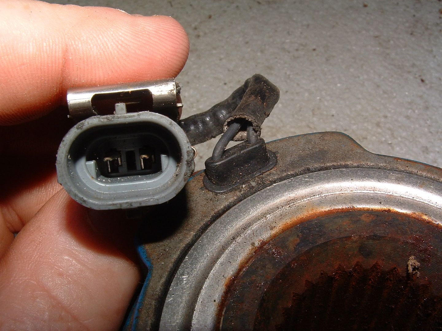
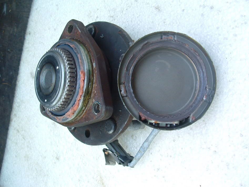
If so,,,it is easy to check the sensor. You can check the resistance of the WSS. Disconnect the connector from the hub and read the pigtail.

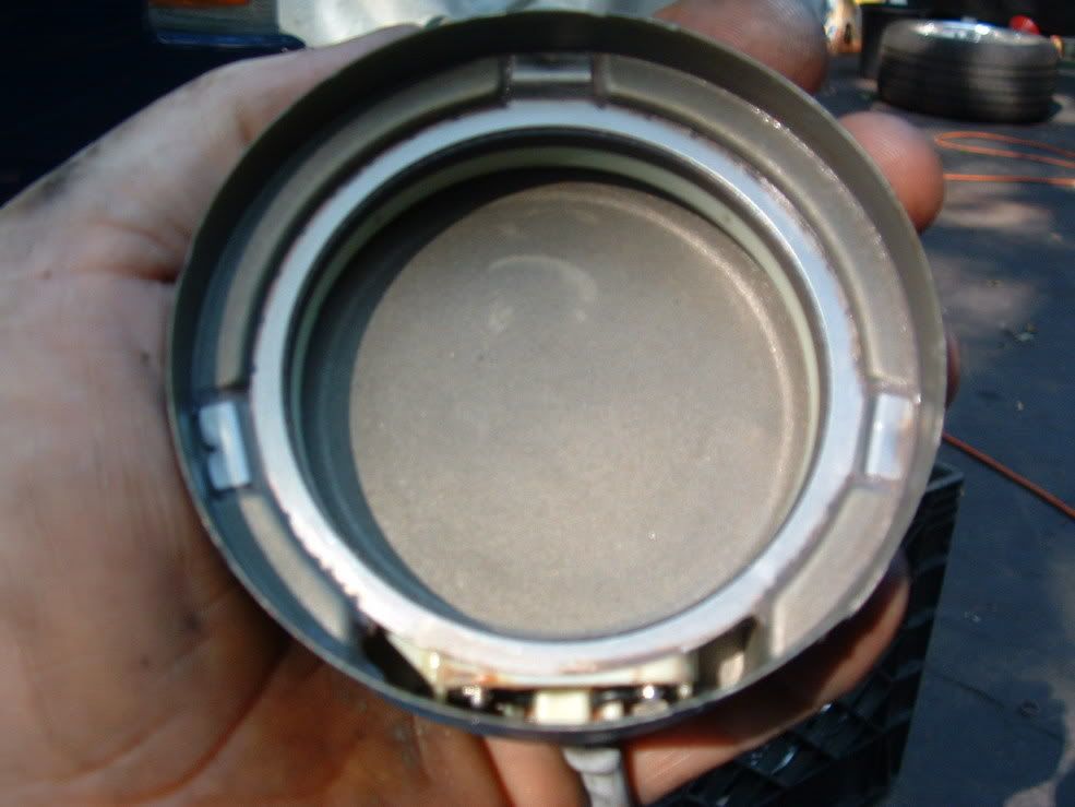
The inside of the sensor is quite simple and almost bullet proof. If you read the correct resistance and can rotate the tire and get an AC voltage out of the sensor,,,theres most likely nothing at all wrong with it.


The resistance that you need to see is: 850-1350 ohms
The voltage you need to see is: Spin the wheel as fast as you can by hand while monitoring the AC output.
Is the AC voltage within the range specified in the value(s) column?
Above 100 mV
The speed sensor used on this vehicle is a single point magnetic pickup. This sensor produces an AC signal that the EBCM uses the frequency from to calculate the wheel speed.
Conditions for Setting the DTC
The DTC will set if one wheel speed = 0 and the other WSS are greater than 8 km/h (5 mph) for 2.5 seconds.
Action Taken When the DTC Sets
ABS/TCS/Active Handling (if equipped with RPO JL4) are disabled.
Indicators that turn on:
ABS indicator
Car Icon (TCS indicator)
Messages displayed on the DIC:
Service ABS
Service Traction System
Service Active HNDLG (if equipped with Active Handling RPO JL4)
Conditions for Clearing the DTC
Condition for DTC is no longer present and scan tool clear DTC function is used.
Fifty ignition cycles have passed with no DTCs detected.
Diagnostic Aids
It is very important that a thorough inspection of the wiring and connectors be performed. Failure to carefully and fully inspect wiring and connectors may result in misdiagnosis, causing part replacement with reappearance of the malfunction.
An intermittent malfunction can be caused by poor connections, broken insulation, or a wire that is broken inside the insulation.
If an intermittent malfunction exists refer to Intermittents and Poor Connections in Wiring Systems.
Test Description
The numbers below refer to step numbers on the diagnostic table.
Checks the resistance of the WSS.
Checks if the WSS CKTs are shorted together.
DTC C1223 LR Wheel Speed Sensor Input is 0 Step
Action
Value(s)
Yes
No
1
Was the Diagnostic System Check performed?
--
Go to Step 2
Go to Diagnostic System Check - ABS
2
Inspect the WSS wiring and connectors for damage.
Inspect WSS for looseness or damage.
Is physical damage of sensor evident?
--
Go to Step 7
Go to Step 3
3
Disconnect the WSS at the sensor pigtail.
Using J 39200 DMM, measure the resistance between terminals A and B of the WSS.
Is the resistance within the range specified in the value(s) column?
850-1350 ohms
Go to Step 4
Go to Step 7
4
With J 39200 DMM still connected, select the mV AC scale.
Spin the wheel as fast as you can by hand while monitoring the AC output.
Is the AC voltage within the range specified in the value(s) column?
Above 100 mV
Go to Step 5
Go to Step 7
5
Disconnect the EBCM harness connector.
Install J 39700 Universal Pinout Box using the J 39700-25 cable adapter to the EBCM harness connector only.
Using J 39200 DMM, measure resistance between terminals 12 and 28 of the J 39700 .
Is the resistance within the range specified in the value(s) column?
850-1350 ohms
Go to Step 6
Go to Step 8
6
Reconnect all connectors.
Carefully test drive vehicle above 24 km/h (15 mph) for at least 30 seconds while monitoring a scan tool.
Does DTC reset as a current DTC?
--
Go to Step 9
Go to Diagnostic System Check - ABS
7
Replace wheel speed sensor. Refer to Wheel Bearing/Hub Replacement - Rear in Rear Suspension.
Is the repair complete?
--
Go to Step 10
--
8
If the resistance was low, repair short between CKTs 884 and 885.
If the resistance was high, check for open in CKTs 884 or 885. Refer to Wiring Repairs in Wiring Systems.
Is the repair complete?
--
Go to Step 10
--
9
Replace EBCM. Refer to Electronic Brake Control Module (EBCM) Replacement .
Is the replacement complete?
--
Go to Step 10
--
10
Carefully test drive vehicle above 24 km/h (15 mph) while monitoring a scan tool for at least 30 seconds.
Does the DTC set as a current DTC?
--
Go to Step 2
Go to Diagnostic System Check - ABS
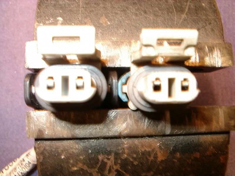
90% of WSS issues deal with connector corrosion or defective female pins. Heres a good and bad WSS female connector. The one on the left is new, the one on the right is BAD:

BC
Thread Starter
Tech Contributor
Joined: Dec 1999
Posts: 32,910
Likes: 2,402
From: Anthony TX
CI 6,7,8,9,11 Vet
St. Jude Donor '08
Hi Bill
The original alarm system on my C5 -01 is not working as it should.
When I lock the car with the FOB only the front turn signals flashes one time and not the backup lamps, and there is no flash at all on any exterior light when I unlock the car.
And if I set of the alarm the horn is pulsing but none of the exterior lights flashes, only the lamps that is located in the rear-view mirror flashes.
I have the settings LOCK & ARM - LIGHTS ONLY and ALARM HORN & LIGHTS in the DIC display.
I have no fault codes in the DIC dispaly.
The backup lights and all other exterior lights works except when the alarm wants to control them.
Any suggestions on what to do, or is does it sound like I have to replace the BCM?
Maybe take a look inside the BCM and look for bad solder points?
BC
Instructor
Joined: Jan 2008
Posts: 213
Likes: 1
From: Portland Maine
DTC U1232???? Are you sue that your reading the DTC Correctly???
I do not see U1232 on my DTC List Are you sure its not "DTC C1223 LR Wheel Speed Sensor Input Signal is 0
If so,,,it is easy to check the sensor. You can check the resistance of the WSS. Disconnect the connector from the hub and read the pigtail.
The inside of the sensor is quite simple and almost bullet proof. If you read the correct resistance and can rotate the tire and get an AC voltage out of the sensor,,,theres most likely nothing at all wrong with it.
The resistance that you need to see is: 850-1350 ohms
The voltage you need to see is: Spin the wheel as fast as you can by hand while monitoring the AC output.
Is the AC voltage within the range specified in the value(s) column?
Above 100 mV
The speed sensor used on this vehicle is a single point magnetic pickup. This sensor produces an AC signal that the EBCM uses the frequency from to calculate the wheel speed.
Conditions for Setting the DTC
The DTC will set if one wheel speed = 0 and the other WSS are greater than 8 km/h (5 mph) for 2.5 seconds.
Action Taken When the DTC Sets
ABS/TCS/Active Handling (if equipped with RPO JL4) are disabled.
Indicators that turn on:
ABS indicator
Car Icon (TCS indicator)
Messages displayed on the DIC:
Service ABS
Service Traction System
Service Active HNDLG (if equipped with Active Handling RPO JL4)
Conditions for Clearing the DTC
Condition for DTC is no longer present and scan tool clear DTC function is used.
Fifty ignition cycles have passed with no DTCs detected.
Diagnostic Aids
It is very important that a thorough inspection of the wiring and connectors be performed. Failure to carefully and fully inspect wiring and connectors may result in misdiagnosis, causing part replacement with reappearance of the malfunction.
An intermittent malfunction can be caused by poor connections, broken insulation, or a wire that is broken inside the insulation.
If an intermittent malfunction exists refer to Intermittents and Poor Connections in Wiring Systems.
Test Description
The numbers below refer to step numbers on the diagnostic table.
Checks the resistance of the WSS.
Checks if the WSS CKTs are shorted together.
DTC C1223 LR Wheel Speed Sensor Input is 0 Step
Action
Value(s)
Yes
No
1
Was the Diagnostic System Check performed?
--
Go to Step 2
Go to Diagnostic System Check - ABS
2
Inspect the WSS wiring and connectors for damage.
Inspect WSS for looseness or damage.
Is physical damage of sensor evident?
--
Go to Step 7
Go to Step 3
3
Disconnect the WSS at the sensor pigtail.
Using J 39200 DMM, measure the resistance between terminals A and B of the WSS.
Is the resistance within the range specified in the value(s) column?
850-1350 ohms
Go to Step 4
Go to Step 7
4
With J 39200 DMM still connected, select the mV AC scale.
Spin the wheel as fast as you can by hand while monitoring the AC output.
Is the AC voltage within the range specified in the value(s) column?
Above 100 mV
Go to Step 5
Go to Step 7
5
Disconnect the EBCM harness connector.
Install J 39700 Universal Pinout Box using the J 39700-25 cable adapter to the EBCM harness connector only.
Using J 39200 DMM, measure resistance between terminals 12 and 28 of the J 39700 .
Is the resistance within the range specified in the value(s) column?
850-1350 ohms
Go to Step 6
Go to Step 8
6
Reconnect all connectors.
Carefully test drive vehicle above 24 km/h (15 mph) for at least 30 seconds while monitoring a scan tool.
Does DTC reset as a current DTC?
--
Go to Step 9
Go to Diagnostic System Check - ABS
7
Replace wheel speed sensor. Refer to Wheel Bearing/Hub Replacement - Rear in Rear Suspension.
Is the repair complete?
--
Go to Step 10
--
8
If the resistance was low, repair short between CKTs 884 and 885.
If the resistance was high, check for open in CKTs 884 or 885. Refer to Wiring Repairs in Wiring Systems.
Is the repair complete?
--
Go to Step 10
--
9
Replace EBCM. Refer to Electronic Brake Control Module (EBCM) Replacement .
Is the replacement complete?
--
Go to Step 10
--
10
Carefully test drive vehicle above 24 km/h (15 mph) while monitoring a scan tool for at least 30 seconds.
Does the DTC set as a current DTC?
--
Go to Step 2
Go to Diagnostic System Check - ABS
90% of WSS issues deal with connector corrosion or defective female pins. Heres a good and bad WSS female connector. The one on the left is new, the one on the right is BAD:
BC
Dave

Cruising
Joined: Feb 2010
Posts: 12
Likes: 0
From: coalburg west virginia
i will most definately clean the grounds. but my problem started after the exhaust was changed. i have a 2004 corvette ls1 it has only 30000 miles on it. everything was fine until the exhaust was changed it started to give me po137 bank one sensor 2 low voltage and po157 ho2s low voltage bank 2 sensor 2 and it also started throwing a b0363 left actuator feedback open. this only occured like i said after the exhaust was changed. i bought 2 new sensors and they were changed but no help. pulled 18 and 27 fuse to resit the actuator door with no help.
Thread Starter
Tech Contributor
Joined: Dec 1999
Posts: 32,910
Likes: 2,402
From: Anthony TX
CI 6,7,8,9,11 Vet
St. Jude Donor '08
i will most definately clean the grounds. but my problem started after the exhaust was changed. i have a 2004 corvette ls1 it has only 30000 miles on it. everything was fine until the exhaust was changed it started to give me po137 bank one sensor 2 low voltage and po157 ho2s low voltage bank 2 sensor 2 and it also started throwing a b0363 left actuator feedback open. this only occured like i said after the exhaust was changed. i bought 2 new sensors and they were changed but no help. pulled 18 and 27 fuse to resit the actuator door with no help.
Check the grounds and make sure that you get a zero reading to chassis ground G-105
Un-plug each O2 sensor and check for proper heater circuit voltages and ground readings. There are two test points on each fuse. Read them to ground with the key in the ON position to see if it getting the full battery voltage at the fuse.
The power for the O2 sensors comes thru the IGNITION Switch. If the voltage is LOW, the contacts in the switch are burnt and need to be cleaned.
BC
Pro


Joined: Oct 2007
Posts: 739
Likes: 52
From: Reno NV
I had my dic flashing no comm etc... I thought because of my doors. I checked the ground G101, G102 and they were filthy covered with pebbles and dirt. I didn't have any corrosion in bills pic, Just dirt and pebbles.
Corvette Stories
The Best of Corvette for Corvette Enthusiasts

Top 10 Most Expensive Corvettes Ever Sold on Bring A Trailer
Brett Foote
10 Things Every Corvette Owner Needs (2026 Edition)
Michael S. Palmer
8 Most "Only Corvette Owners Understand" Quirks and Problems
Pouria Savadkouei
10 Reasons the C6 Z06 is Still A Performance Benchmark After 20 Years
Joe Kucinski
How Much Horsepower Every Corvette Engine "LOST" in 1972
Joe Kucinski
Top 10 DOs and DON'Ts for Protecting Your Convertible Top!
Michael S. Palmer
Top 10 Most Explosive Corvettes Ever Made: Power-to-Weight Ratio Ranked!
Joe Kucinski
150 hp to 1,250 hp: Every Corvette Generation Compared by the Specs That Matter
Joe Kucinski
8 Coolest Corvette Pace Cars (and Replicas) of All Time
Verdad Gallardo
Intermediate
Joined: Oct 2009
Posts: 30
Likes: 0
Originally Posted by LNZ
Hi Bill
The original alarm system on my C5 -01 is not working as it should.
When I lock the car with the FOB only the front turn signals flashes one time and not the backup lamps, and there is no flash at all on any exterior light when I unlock the car.
And if I set of the alarm the horn is pulsing but none of the exterior lights flashes, only the lamps that is located in the rear-view mirror flashes.
I have the settings LOCK & ARM - LIGHTS ONLY and ALARM HORN & LIGHTS in the DIC display.
I have no fault codes in the DIC dispaly
The backup lights and all other exterior lights works except when the alarm wants to control them.
Any suggestions on what to do, or is does it sound like I have to replace the BCM?
Maybe take a look inside the BCM and look for bad solder points?
The circuit for the front turn signals is also OK because it�s working when I lock the car.
I think the problem is a bad BCM, I can live whit no flashing during an alarm, but how worry should I be that the BCM will get worse and cause more problems?
Should I replace the BCM or can I leave it as it is?
Thread Starter
Tech Contributor
Joined: Dec 1999
Posts: 32,910
Likes: 2,402
From: Anthony TX
CI 6,7,8,9,11 Vet
St. Jude Donor '08
I have measured from the BCM connector to the backup lamps relay and that wire is OK.
The circuit for the front turn signals is also OK because it�s working when I lock the car.
I think the problem is a bad BCM, I can live whit no flashing during an alarm, but how worry should I be that the BCM will get worse and cause more problems?
Should I replace the BCM or can I leave it as it is?
Check out this circuit. Check relay #38 (Back Up Relay) in the under hood fuse box and fuse: #2 (Approach) You can simulate the BCM operation by GROUNDING "Dark Blue" wire on the relay. If it works when you ground that wire,,,the wireing from the BCM to the relay is bad OR the BCM driver circuit is bad.
BC
If the relay is suspect, swap it with one of the same number.
Intermediate
Joined: Oct 2009
Posts: 30
Likes: 0
The relay circuit 38 is OK, the backup lamps turns on when grounding the dark blue wire.
But the circuit for the front turn signals works when I lock the car and not when unlocking or during an alarm, so the wiring is OK and the BCM driver circuit is OK.
Or does the turn signal come from any outer source then the BCM when locking?
But the circuit for the front turn signals works when I lock the car and not when unlocking or during an alarm, so the wiring is OK and the BCM driver circuit is OK.
Or does the turn signal come from any outer source then the BCM when locking?
Thread Starter
Tech Contributor
Joined: Dec 1999
Posts: 32,910
Likes: 2,402
From: Anthony TX
CI 6,7,8,9,11 Vet
St. Jude Donor '08
The relay circuit 38 is OK, the backup lamps turns on when grounding the dark blue wire.
But the circuit for the front turn signals works when I lock the car and not when unlocking or during an alarm, so the wiring is OK and the BCM driver circuit is OK.
Or does the turn signal come from any outer source then the BCM when locking?
But the circuit for the front turn signals works when I lock the car and not when unlocking or during an alarm, so the wiring is OK and the BCM driver circuit is OK.
Or does the turn signal come from any outer source then the BCM when locking?
Heres a post on turn sig switch repair;
- http://forums.corvetteforum.com/c5-t...f-replace.html
BC
Bill
Intermediate
Joined: Oct 2009
Posts: 30
Likes: 0
The front turn signals should flash (and the backup lamps) when lock or unlock the car with the fob, and they should flash during an alarm also, but in my case it only flash one time when locking the car not when unlocking or during an alarm.
The backup lamps does�t flash at all when lock/unlock or during an alarm.
The turn signals working when using them from my multifunction switch but not when the alarm tries to control them.
The backup lamps does�t flash at all when lock/unlock or during an alarm.
The turn signals working when using them from my multifunction switch but not when the alarm tries to control them.
Last edited by LNZ; Feb 11, 2010 at 07:10 AM.
Thread Starter
Tech Contributor
Joined: Dec 1999
Posts: 32,910
Likes: 2,402
From: Anthony TX
CI 6,7,8,9,11 Vet
St. Jude Donor '08
Yea,,,that sounds like a BCM issue. I would remove the BCM , examine the connectors and wiring, and remove the BCM Circuit board from the box and insure that theres no corrosion on the board. If all that fails, consider a New BCM. Remember,,,Its NOT plug and play. You need to sync it with the PCM and if you find that some of your RPO options no longer function, you will need to find a TECH II to program them back in the BCM.
BC
BC
Intermediate
Joined: Oct 2009
Posts: 30
Likes: 0
Can I leave the problem and live whit it, or is this the beginning of worse problems?
Yes I know it�s hard to say from case to case but maybe there is some outer members here that have some experience of strange BCM behaviour that getting worser by time?
EDIT:
I have the European model and what I have heard I can�t program the BCM even if I find a Tech II because I need a code that only GM have.
And a replacement done by a GM shop is very expensive.
Last edited by LNZ; Feb 11, 2010 at 11:28 AM.
Thread Starter
Tech Contributor
Joined: Dec 1999
Posts: 32,910
Likes: 2,402
From: Anthony TX
CI 6,7,8,9,11 Vet
St. Jude Donor '08
Can I leave the problem and live whit it, or is this the beginning of worse problems?
Yes I know it�s hard to say from case to case but maybe there is some outer members here that have some experience of strange BCM behaviour that getting worser by time?
EDIT:
I have the European model and what I have heard I can�t program the BCM even if I find a Tech II because I need a code that only GM have.
And a replacement done by a GM shop is very expensive.
Yes I know it�s hard to say from case to case but maybe there is some outer members here that have some experience of strange BCM behaviour that getting worser by time?
EDIT:
I have the European model and what I have heard I can�t program the BCM even if I find a Tech II because I need a code that only GM have.
And a replacement done by a GM shop is very expensive.
"EDIT:
I have the European model and what I have heard I can�t program the BCM even if I find a Tech II because I need a code that only GM have.
And a replacement done by a GM shop is very expensive.[/QUOTE]
You can purchase a new BCM and install it. Then you can flash it to get it to sync with the PCM. Then all you need to do is have the dealer up-date the necessary RPO Codes. It should take less than an hours labor.
Yess you can live with it. It may get wore and then it may stay the same or one day, it may wok normal again. No telling.
BC

6th Gear
Joined: Jun 2008
Posts: 6
Likes: 0
From: lake forest CA
Bill
i have read through all the posts that would relate to my issue and have started to clean all the grounds.. I have cleaned out my drivers door ground and the grounds by my battery and frame and the others but none on the block itself... what should be some steps to trouble shoot this. Could it just be a bad pcm or do you think it could be a ground issue.
I first noticed the issue when i would get a charge fault error on my dash. then a while later my drivers side window stopped working and within a few minutes all my gauges and faults were set off.. I cannot roll up my window and my drvers side electric locks dont light up or work...When i open and close my driver side door it throws all the computer codes haywire and when i get into my car with the door closed and then turn my car on there is no issue... The passenger side is fine.... anyone have any suggestions... i cleaned 4 of the thirteen grounds so far. Here is a list of my codes there were to many to write down so here are the categories... also my hvac code cannot be reset and the ac control lights sometimes wont go off when i turn my car off...
Codes shown are
10pcm 1 code
28tcs 4 codes
40 bcm no comm
60IRC 5 codes
80 radio 3 codes
99 hvac no comm
agcdcm no comm
a1 rdcm no comm
a1rdcm 7 codes
a6 scm 6 codes
60 IPC
I can clear codes manually but they come back....
Last edited by jonharper55; Feb 22, 2010 at 10:45 PM.

Racer
Joined: May 2006
Posts: 352
Likes: 42
I've seen many posts from folks asking how to tell if their battery is good. Today I ran across this site that should be useful. Go here http://www.batteryfaq.org/ and then scroll down to the link that says "Temperature Compensated Battery State-of-Charge (SoC) Table". It's an excel file that shows the proper voltages for a battery in different states of charge from 0% to 100% at various temperatures. Note that this is an open circuit voltage so you'll need to disconnect one side of the battery to use this table. (It's safest to disconnect the negative side!)
Hope that helps someone. This forum has certainly helped me MANY times!
Save the wave!
DocOhm
Hope that helps someone. This forum has certainly helped me MANY times!
Save the wave!
DocOhm

7th Gear
Joined: Mar 2010
Posts: 7
Likes: 0
From: Patterson La.
Help, have 97 and can't clear PCM P1571 HC, also TCS C1277 and B2278, I read the thread on cleaning the ground connectors, have done it. Also I had a service vehicle soon, checked and I had a loose connection on the battery, tightned everything up and they all went away, except the P1571, C1277 and B2278, any ideas anyone