


IMPORTANT ELECTRICAL INFORMATION (Long!)

Thread Starter
Tech Contributor


Joined: Dec 1999
Posts: 32,910
Likes: 2,402
From: Anthony TX
CI 6,7,8,9,11 Vet
St. Jude Donor '08
The chassis ground points are MIRROR located. If you find one on the drivers side, there is an identical one on the same place on the passengers side.
There are THREE ground points on the engine. Two on the sides of the block and one on the back of the drivers head.
There are FOUR inside the cabin. At the base of the door A pillar and behind the seat near the seat belt retractor asembly. The ones in the cabin require door sill cover removal and the trim over the seat belt retractor removal.
The ones in the cabin are 9 times out of 10 NOT an issue.
The only C5 that uses chassis ground G-402 are 97 and 98 C5s that have rear mounted EBTCM. All other C5 that stud is not used and has a rubber cap over it.
BC
Thread Starter
Tech Contributor
Joined: Dec 1999
Posts: 32,910
Likes: 2,402
From: Anthony TX
CI 6,7,8,9,11 Vet
St. Jude Donor '08
Thread Starter
Tech Contributor
Joined: Dec 1999
Posts: 32,910
Likes: 2,402
From: Anthony TX
CI 6,7,8,9,11 Vet
St. Jude Donor '08
Make sure that you tell them the reason your bringing it.
The correct way to test it would be to use an oscillascope but, most people dont have one. The meter isnt fool proof but, its a good quick test.
NEXT. Use te same meter set to DC Volts. Put the positive lead on the BATT terminal on the back of alternator and the NEG terminal on the POSITIVE battery terminal.
You "SHOULD" read ZERO VOLTS DC. If you read any voltage the connection between the battery POS and the alternator is faulted. Most likely at the solenoid main terminal.
BC

Advanced

Joined: Jul 2011
Posts: 62
Likes: 1
Your generator outputs DC Voltage. IF,, the rectifers inside are not working properly, thay can pass AC. Use an AC Voltmeter and read the large BATT terminal to chassis ground. You SHOULD read ZERO AC VOLTS. If you read any AC volts, I would take the alternator to a Starter/Alternator rebuild shop and have them rebuild it.
Make sure that you tell them the reason your bringing it.
The correct way to test it would be to use an oscillascope but, most people dont have one. The meter isnt fool proof but, its a good quick test.
NEXT. Use te same meter set to DC Volts. Put the positive lead on the BATT terminal on the back of alternator and the NEG terminal on the POSITIVE battery terminal.
You "SHOULD" read ZERO VOLTS DC. If you read any voltage the connection between the battery POS and the alternator is faulted. Most likely at the solenoid main terminal.
BC
Thread Starter
Tech Contributor
Joined: Dec 1999
Posts: 32,910
Likes: 2,402
From: Anthony TX
CI 6,7,8,9,11 Vet
St. Jude Donor '08
Advanced
Joined: Jul 2011
Posts: 62
Likes: 1
Ok So I lack a lot of knowledge when it comes to electrical. You wanting me to put the positive lead where the red wire connects on the starter solenoid? I appreciate the patience and help.
Last edited by MOTOXAZ; Dec 23, 2015 at 07:10 PM.
Corvette Stories
The Best of Corvette for Corvette Enthusiasts

Top 10 Most Expensive Corvettes Ever Sold on Bring A Trailer
Brett Foote
10 Things Every Corvette Owner Needs (2026 Edition)
Michael S. Palmer
8 Most "Only Corvette Owners Understand" Quirks and Problems
Pouria Savadkouei
10 Reasons the C6 Z06 is Still A Performance Benchmark After 20 Years
Joe Kucinski
How Much Horsepower Every Corvette Engine "LOST" in 1972
Joe Kucinski
Top 10 DOs and DON'Ts for Protecting Your Convertible Top!
Michael S. Palmer
Top 10 Most Explosive Corvettes Ever Made: Power-to-Weight Ratio Ranked!
Joe Kucinski
150 hp to 1,250 hp: Every Corvette Generation Compared by the Specs That Matter
Joe Kucinski
8 Coolest Corvette Pace Cars (and Replicas) of All Time
Verdad Gallardo
Thread Starter
Tech Contributor
Joined: Dec 1999
Posts: 32,910
Likes: 2,402
From: Anthony TX
CI 6,7,8,9,11 Vet
St. Jude Donor '08
No... The JUNCTION on the solenoid or the FUSE in the wire coming from alternator "COULD" be loose, burnt, corroded ect.
You will become Stretch Armstrong and put the DC Meter RED Lead on the back of the ALTERNATOR BATT Terminal and the other on the POSITIVE terminal on the BATTERY.
Its easier to get a helper.
What you are doing is looking for a VOLTAGE DROP across that circuit, meaning a lously connection. In a PERFECT C5 WORLD,, the reading that you should see is ZERO. Report the reading:
ENGINE OFF
ENGINE RUNNING
Just for grins and to get a better idea how your electrical system is working, read the battery voltage directly on the battery terminals:
ENGINE OFF
ENGINE RUNNING
Bill
Last edited by Bill Curlee; Dec 23, 2015 at 08:07 PM.
Thread Starter
Tech Contributor
Joined: Dec 1999
Posts: 32,910
Likes: 2,402
From: Anthony TX
CI 6,7,8,9,11 Vet
St. Jude Donor '08
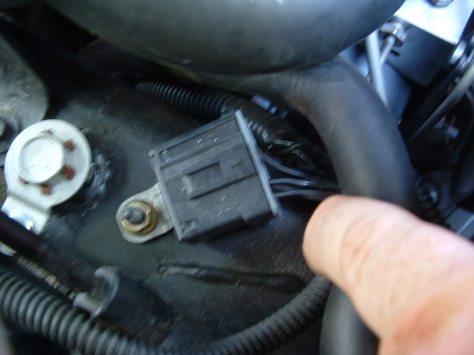
The POSITIVE Meter lead on the connection on the back of the alternator (BATT TERMINAL) & the NEGATIVE LEAD on any good chassis (bare metal) ground. Clean with a wire brush.
Good ground connection area:
Good ground connection area:
Burning Brakes


Joined: Oct 2013
Posts: 1,030
Likes: 72
From: Seminole, FL
Thought I might help out a little here?
Using Bill's original photo of the starter cable studs.
I've added my own starter, which is a 99 Coupe.
Suddenly started having trouble starting the car, intermittently.
Battery was 9 years old, so I replaced it.
Problem 'appeared' to be solved.
Days later same problem... "INTERMITTENT"..
Bought starter, pulled mine.
Battery / Power Cable stud nut on starter wasn't tightened enough and the connection was rusty, and BURNT.
Cleaned up all the cables and the starter and replaced the nut.
Problem solved. Kept my starter and got my refund on the unused new starter.

 Your the man! Mad computer skills!!!!!!!

Instructor

Joined: Aug 2012
Posts: 194
Likes: 15
From: Orange County CA
Thanks Bill, this is pretty wonderful to have this resource. At the risk of asking a dumb question, what information does the legend to the schematic give me. Example: by the right front headlight (4) G102. Other than knowing the location of a groundpoint does G102 send me to somewhere in the manual for more information? Thanks, Bob
Thread Starter
Tech Contributor
Joined: Dec 1999
Posts: 32,910
Likes: 2,402
From: Anthony TX
CI 6,7,8,9,11 Vet
St. Jude Donor '08
Thanks Bill, this is pretty wonderful to have this resource. At the risk of asking a dumb question, what information does the legend to the schematic give me. Example: by the right front headlight (4) G102. Other than knowing the location of a groundpoint does G102 send me to somewhere in the manual for more information? Thanks, Bob
Bob
Once,,, I was a C5 NUBEE... My 1998 C5 coupe FAILED electrically shortly out of warranty.
 I had to ask a lot of forum questions and become ONE with the Service Manual to understand what as defective and how to resolve it.
 Heres is a FREE On-Line service manuals. Its excellent: http://www.bbbind.com/free_tsb.html
To use the Service manual effectively, you:
1. You have to figure out how GM References each Volume. Then what is in each section/chapter. Each section is then layer out in a general view and then it gets more detailed.
So, I you wanted to see what G-102 goes to, you would go to SYSTEM (Electrical Distribution), Then SUBSYSTEM (Ground Distribution) Then you just go down through the pages . G-102 is only DOT on the schematic which is part of splice pack SP-100.
SP-100 fingers out to every MODULE & or component that is attached (grounded) to G-102/SP-100.
When you go to a component page for a single part, like the passengers head light motor, that page will reference or point to the motor being grounded to G-102. You will also see the head light motor BOX on the G-102/SP-100 Ground Distro page.
There is a GENERAL section and sometimes that references specific information for making a proper connections, how to read symbols, soldering etc.
Grab one of the three Book/Volumes and page thru each section and see what’s in it and how its layed out. Once you get familiar with what each book contains and what each chapter/section contains, you will be able to see a volume, go to a section and find a component.
It takes a while to get use to them. TRUST ME.
Oh,, once you get the C5 Service manual memorized and figured out, You will purchase a C6 and then have to figure out Those Service manuals ALL OVER AGAIN!
 They are layed out the same but, how the schematics are drawn/layed out is different than the C5 schematics.
Then you own a Chrysler / Jeep and those are way different.
Bill
Last edited by Bill Curlee; Jan 3, 2016 at 08:09 AM.
Instructor
Joined: Aug 2012
Posts: 194
Likes: 15
From: Orange County CA
Yikes, I see what you are saying and it sounds like I may be in for another case of information overload, lol. And yes, I'm hoping in the not too distant future to have a C7 so my journey is just beginning. Thanks very much Bill. Bob
Thread Starter
Tech Contributor
Joined: Dec 1999
Posts: 32,910
Likes: 2,402
From: Anthony TX
CI 6,7,8,9,11 Vet
St. Jude Donor '08
I was seriously overwhelmed using the manuals when I first received them. I had HUNDREDS of yellow stickies sticking out of the manuals referencing something that was important.
I don't have those yellow stickies any more as I am a lot more familiar with how to find what I'm looking for. It will come over time.
I don't have those yellow stickies any more as I am a lot more familiar with how to find what I'm looking for. It will come over time.
