C6 C7 Corvette: How to Bleed Hydraulic Clutch System
When your clutch fluid consistently looks dirty or cloudy, bleeding your clutch may be necessary. Learn how to DIY here.
This article applies to the C6 and C7 Corvette (2005-current).
Even though today’s automatic transmissions have gained in both the number of gears and electronically-controlled shift response times, many full-time Corvette enthusiasts hold onto their belief that only if it includes a manual transmission can any two-seater vehicle be called a true sports car. Be that as it may, while the manual transmission seem to be going the way of the dinosaurs (only one pickup truck model still offers a manual), 35% of the Corvettes sold during the 2013 and 2014 model years were built around manual transmissions.
Manual transmissions utilize a hydraulic clutch system consisting of a hydraulic fluid reservoir located under the hood, a master cylinder controlled by the clutch, and a hydraulic piston called the slave cylinder, clutch actuator, or actuator cylinder. On many cars, the slave cylinder is conveniently located on the outside of the transmission, but on the Corvette, it is not conveniently located — it’s in the bell-housing by the flywheel.
Routine clutch maintenance consists of what’s commonly called the “turkey baster” or “Ranger” method. This involves using a large syringe to extract the murky-looking hydraulic fluid from the reservoir, replacing it with new fluid, capping the reservoir, pumping the clutch pedal to the floor thirty times or so, then rechecking the fluid’s appearance. If it still looks murky, you must repeat this routine until it’s clear.

Materials Needed
- An assistant, if not for the disassembly of the intermediate exhaust pipes, then for the actual clutch bleed procedure
- Large disposable plastic cups for dirty fluid
- Lint-free paper towels
- Rubber gloves
- Car jacks
- Long-handle half-inch metric socket set
- Small quarter-inch metric socket set
If after performing this routine clutch issues remain, such as the clutch pedal wanting to...
- Stick to the floor
- Hang up in mid-travel
- Return too slowly
- Feel too hard or too soft
...then your clutch fluid is probably contaminated (with water, or dust, or both), and you may need to bleed the clutch. Another reason to perform a clutch bleed is if the hydraulic fluid has completely run dry, which can also indicate a leak in the hydraulic system.
A clutch bleed is the “court of last resort” for serious clutch problems. If the bleed doesn’t satisfy your clutch, a more serious remedy, such as replacing the slave cylinder, may be required (a lengthy and expensive proposition).
To bleed the clutch, begin with the same procedure as the “turkey baster” or “Ranger” method:
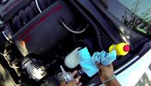
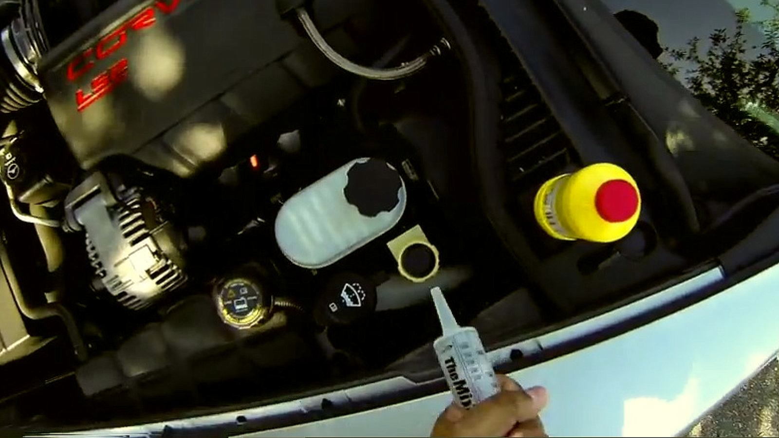
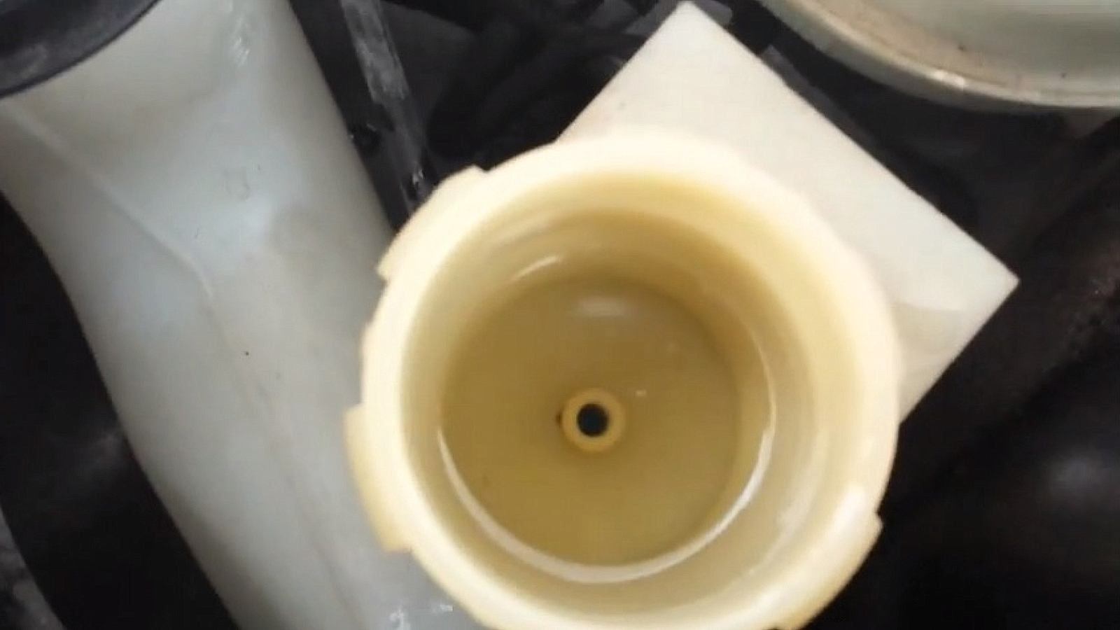
Step 1 – Replace the fluid in the master cylinder reservoir with clean fluid
Clean the area around the clutch fluid cap, as well as the cap itself, to prevent dirt from getting into the hydraulic fluid when the cap is removed. Remove the cap and diaphragm and, with the syringe, empty the fluid out of the master cylinder.
Then, with a lint-free paper towel, wipe the inside and bottom of the master cylinder clean.
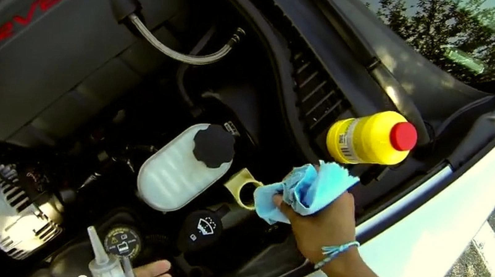
Fill the reservoir with Super DOT4 or equivalent to just below the fill line. Recap the reservoir.
Pro Tip
Punch a small hole in the DOT4 bottle’s top seal to help control the pour amount going into the master cylinder. Recap the bottle tightly when not in use, as dust, moisture, and exposure to air will ultimately contaminate this fluid.
Step 2 – Remove the intermediate exhaust pipes
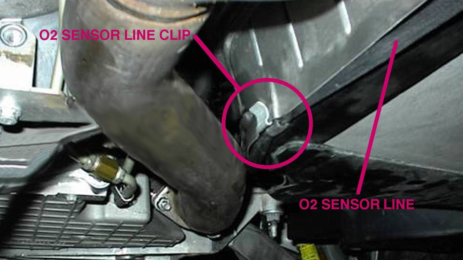
To bleed the clutch, the maintenance procedure now becomes much more physical. First, disconnect the negative wire from the battery, then disconnect the two O2 sensor lines going to the pipes aft of the catalytic converters. The O2 sensor harnesses are located near where the pipes connect to the exhaust manifolds. You must first remove their retaining pins to unplug them.

Remove the retaining clips holding the O2 sensor wires up on either side of the driveline tunnel.
With a 15mm socket, remove the three nuts that hold each exhaust pipe flange to its exhaust manifold. Prop these flanges up from underneath with spacers (such as sturdy boxes) before removing (with the 15mm socket) the two bolts per exhaust pipe at the other end of the exhaust pipe. Prop this end up as well.

Step 3 – Remove the forward and rear exhaust hangers
Remove the two 15mm bolts holding on the forward exhaust hanger, located just behind the bell-housing. Then, remove the two 13mm bolts holding on the rear exhaust hanger, and lower the rear of the pipes to the floor. Take the spacer out from beneath the front of the pipes and lower them to the floor as well. Slide the exhaust assembly out from under the car and out of the way.

Step 4 – Remove the driveline tunnel closeout panel
Remove the 36 (yes, 36) 8mm bolts holding up the driveline tunnel closeout panel. Again, prop up the front of the panel as you make your way to the rear of the panel (you don’t want the panel to bend). When all bolts are removed, lower the panel to the floor and move it out from under the car. The torque tube is now exposed.

Step 5 – Locate the clutch bleeder screw
Reach up and around the engine-end of the torque tube to find the clutch bleeder screw, a short, two-inch tube with a hex-shaped cap that connects to the slave cylinder inside the bell-housing. This screw is barely accessible, with its hard-to-reach cap loosened with a 9mm thin-wall socket — small tools and skinny fingers work best here. Note that some of the hydraulic fluid that you bleed from this connection will get inside the bell-housing, but it will drip out a small drain hole in the bottom of the bell-housing’s inspection plate, just below the bleeder screw.

Step 6 – Bleed the clutch using the bleeder screw
The actual clutch bleeding operation is best done with two people — one in the vehicle, and one under it. Place a shallow pan under the rear of the bell-housing to catch fluid. The person in the car works the clutch and keeps fluid in the master cylinder reservoir, and the one under the car opens the bleeder screw and closes it.

With the reservoir full to its line and its cap tightly in place, have the person in the car pump the clutch in and hold it there. The person under the car unscrews the bleeder cap, 1/8 to 1/4 turn only.
Warning
DO NOT remove the bleeder cap. if removed, the activated clutch pedal will shoot fluid across the torque tube tunnel, into the bell-housing, and down along the screw-loosener’s arm. This fluid is not only caustic (it removes paint), it is also flammable.
After a solid stream of fluid comes out of the bleeder screw — no air, no fizz, no bubbles — re-tighten the cap. Only after the screw has been re-tightened should be the clutch pedal be released.
GM recommends repeating this seven to ten times, or until all air or murky fluid is removed from the system. After every three our four bleeds, remember to refill and recap the reservoir — the idea is to get all air out of the system, not let more air in.
When clutch bleeding is finished, make sure the reservoir is filled to just below the full line, and reattach the cap to its locking position.

Step 7 – Re-assemble
Put the Corvette back together:
- Driveline tunnel closeout panel — 36 8mm bolts; tighten all to 7 lb-ft (10 Nm).
- The forward and rear exhaust hangers.
- Forward exhaust hanger — two 15mm bolts; tighten to 37 lb-ft (50 Nm).
- Rear exhaust hanger — two 13mm bolts; tighten to 37 lb-ft (50 Nm).
- Intermediate exhaust pipes — three 15mm nuts on the front, two 15mm nuts on the rear; tighten all to 37 lb-ft (50 Nm).
Related Discussions
- How to Bleed Clutch Hydraulics - CorvetteForum.com
- Bleeding My Clutch - CorvetteForum.com
- Access to Clutch Bleed Screw - CorvetteForum.com
- Take Care of Your Clutch - CorvetteForum.com
- Installing a Remote Bleeder - CorvetteForum.com