When you click on links to various merchants on this site and make a purchase, this can result in this site earning a commission. Affiliate programs and affiliations include, but are not limited to, the eBay Partner Network.
And the 2 of us are complete opposites. He has years of experience on the track. Runs a fully set up car.
Me, I'm just a poor guy who bought my C3 many, many years ago. And if it wasn't for the help of friends many times over the years. I wouldn't be able to keep it on the road. I occasionally go to club track days. But we're just some old guys cruising around the track having a bit of fun. Nothing serious.
He has the fully welded and gusseted frame with all the good stuff. I just do my best one modification at a time. When I can afford to.
So, it's interesting that we come up with similar observations.
And what this does mean however is that almost without exception. I do one modification at a time. Generally with some time inbetween. So I can actually evaluate each mod.
I haven't tried different rear sway bars. Can't justify the cost if the one I have is working. I haven't tried many different shocks. I'm pretty happy with the Bilstien's and there plenty expensive when your overseas.
I can state with great confidence that the spreader bar really makes a huge difference for the better for us guys with a realitivly stock car.
Overall I am following this thread with great interest as I am always interested in making my car handle better, stick better in the turns. But without a huge budget to try lots of things. Hopefully we can all learn from one another.
The .110" thick steel used to make the frame is not any thicker or stronger than the engineers thought it needed to be, in 1962, With tires of that era. And they knew it had some flex, they measured it. It was a lot less than the 61 frame, and they even tried a thicker frame, but felt the ticker one "affected the ride" and was "unnecessary".
At least they completely boxed it in. The frame was designed with 5" wide tires in mind. Today we put 8-9-10-11" wide tires on it. Street performance tires of today have way more traction than even the Goodyear Bluestreak racing tires of yesteryear. I recall .6 Gs or so for stock cars back then, more with race tires of course, but I measured 1.29G on my DOT "0" autocross specials, way back in in 1990. I found a crack in my frame, below and inside of the right lower front frame horn, near where GM said to add the gussets for racing. I have seen numerous pics online of the lower a-arm mounts tearing completely off the frame. I bent my rear diff crossmember rather easily with a 2.5 lb hammer trying to remove it from the frame, much easier to dent it than I expected. The torsional stiffness rating of new high performance unit body cars is less than 20% of what GM measured our frame at. So with all that in mind, I would say yeah, our frame is marginal for high performance use today, and it is going to flex enough that you can feel it. Not very scientific, just too many observations leading to that conclusion.
Here is a 1963 chart from GM that shows how much flex the frame has in a large bump. 1500# would be a strong.5G bump, but doable. 1/8" of an inch of flex. You can feel this.
Here is the torsional twist chart from 1963 that the engineers were so proud of. It shows how much the frame twists in a corner, under 1000lb load. 1000 lb on one point on a front tire would be about equivalent to a 1.0G turn. The front a-arms mounts would twist by 0.4*. That would change the camber you set during alignment. That is a1/2" upward movementat the a-arm mounting location. Yeah I would say these old frames twists just a bit.
Torsional twisting figures for the best of the new cars can reach 30,000-40,000 Nm/degree (M3, Camaro, CTS, R-8, M-B). (Sorry a C7 is not there it is only at 19,700Nm). (Even Ferraris do not go that high except the F50) That is equal to 20,000 to 30,000 lbs/degree in 1962 english units. New cars can be up to TEN TIMES stiffer than our old corvette antiques. Find a new car where the doors shut with a "thud" and you have found a stiff car. On new cars they even switch to HZ, which is a vibration frequency. You know like tool steel which rings vs normal steel which doesn't.
So yeah anything you can do to stiffen the chassis will be good, you may even feel it, just do not expect miracles, unless you add a full 8 point roll cage. IMHO the full seam welding of the OEM stich welding would make a noticeable difference here.
Now I have seen a new $10k frame at the carlisle made by ??? that was all round tubing. I would love to see a twist number on that one! It should be a huge improvement!
Last edited by leigh1322; Jul 14, 2024 at 10:14 AM.
From: I tend to be leery of any guy who doesn't own a chainsaw or a handgun.
Originally Posted by leigh1322
The .110" thick steel used to make the frame is not any thicker or stronger than the engineers thought it needed to be, in 1962, With tires of that era. And they knew it had some flex, they measured it. It was a lot less than the 61 frame, and they even tried a thicker frame, but felt the ticker one "affected the ride" and was "unnecessary".
At least they completely boxed it in. The frame was designed with 5" wide tires in mind. Today we put 8-9-10-11" wide tires on it. Street performance tires of today have way more traction than even the Goodyear Bluestreak racing tires of yesteryear. I recall .6 Gs or so for stock cars back then, more with race tires of course, but I measured 1.29G on my DOT "0" autocross specials, way back in in 1990. I found a crack in my frame, below and inside of the right lower front frame horn, near where GM said to add the gussets for racing. I have seen numerous pics online of the lower a-arm mounts tearing completely off the frame. I bent my rear diff crossmember rather easily with a 2.5 lb hammer trying to remove it from the frame, much easier to dent it than I expected. The torsional stiffness rating of new high performance unit body cars is less than 20% of what GM measured our frame at. So with all that in mind, I would say yeah, our frame is marginal for high performance use today, and it is going to flex enough that you can feel it. Not very scientific, just too many observations leading to that conclusion.
Here is a 1963 chart from GM that shows how much flex the frame has in a large bump. 1500# would be a strong.5G bump, but doable. 1/8" of an inch of flex. You can feel this.
Here is the torsional twist chart from 1963 that the engineers were so proud of. It shows how much the frame twists in a corner, under 1000lb load. 1000 lb on one point on a front tire would be about equivalent to a 1.0G turn. The front a-arms mounts would twist by 0.4*. That would change the camber you set during alignment. That is a1/2" upward movementat the a-arm mounting location. Yeah I would say these old frames twists just a bit.
Torsional twisting figures for the best of the new cars can reach 30,000-40,000 Nm/degree (M3, Camaro, CTS, R-8, M-B). (Sorry a C7 is not there it is only at 19,700Nm). (Even Ferraris do not go that high except the F50) That is equal to 20,000 to 30,000 lbs/degree in 1962 english units. New cars can be up to TEN TIMES stiffer than our old corvette antiques. Find a new car where the doors shut with a "thud" and you have found a stiff car. On new cars they even switch to HZ, which is a vibration frequency. You know like tool steel which rings vs normal steel which doesn't.
So yeah anything you can do to stiffen the chassis will be good, you may even feel it, just do not expect miracles, unless you add a full 8 point roll cage. IMHO the full seam welding of the OEM stich welding would make a noticeable difference here.
Now I have seen a new $10k frame at the carlisle made by ??? that was all round tubing. I would love to see a twist number on that one! It should be a huge improvement!
I've seen those frames mentioned several times over the years, but other than the bling factor, the weight and torsion specs are never discussed. We're in total agreement that higher torsion strength is desirable , but so far it seems to be a guessing game for what torsional improvement is available and what the offsetting weight penalty is.
Edit: The spreader bar discussion has got me thinking. I've pondered for years adding one, but between the packaging issue with a BB and the uncertainly that it's a definite improvement (and worth the weight), I haven't made any real progress on one. But, I may make a test bar that telescopes so that I could measure the peak amount that the frame area actually flexes. I have a C4 suspension on my car, so my results will be different than stock frame measurements, but if I can get some decent measurements/data I can finally decide if this non-zero weight item is worth adding on my particular setup.
Last edited by 69427; Jul 14, 2024 at 02:04 PM.
Reason: Added content.
Back to the spreader bar and solid motor mounts,
I installed both on my car.
My reasoning to have both is that the solid motor mounts cause the engine to be part of the frame itself and they distribute the engine torque throughout the frame
The engine is mounted farther back and lower in the chassis than the location of the spreader bar.
The spreader bar is mounted forward and higher than the engine and I believe its main purpose is to reduce or eliminate the flex between the shock towers during cornering only.
My installation instructions state they are installed hand tight only so they do not affect the front suspension alignment specs.
Well a spreader bar certainly can not hurt.
If the frame is stock it apparently makes a driver noticeable improvement.
Now if you have done all the other stiffening measures, welded seams, gussets, solid motor mounts, etc. then who knows?
Someone should do a test to see if it still moves and the spreader bar can help.
Thanks to 69427 we may get that info!
Thanks.
Unless can anyone remember where that go-pro video was of the loose spreader bar moving? Was it Ignatz?
Can anyone provide an opinion on how the car should feel at 55mph with the after-alignment settings? (brand new BFG 225/70r15) I'm not giving my opinion on how I think it drives because I may have other issues going on.
I'm not thrilled with the caster (2� & 1.3�) just from the reading here on the forum. If I were to use this as a starting point, what effect on toe and camber would a move of A-arm shims from front to rear be? Is there a rough guideline for the amount of caster change for a specific shim thickness?
Originally Posted by Bikespace
That'll be twitchy, and probably pretty scary at 55 mph. Does it feel like you are riding down the road while balancing on a rail under your car?
It feels like it wanders very easily at 55 and requires pretty frequent corrections. My '67 doesn't feel this way at all, but I don't have any alignment specs on it - wonder how much it would be to just take it in for a set of readings...
Originally Posted by gkull
On that alignment I would say that they didn't try very hard.
...
Side to side equal is very important. I've heard the old BS that they did that for allow for the crown on the road. We know that you turn both left and right and want the car to do each direction equally . Well you ask for easy to do specific numbers and didn't get them.
Stock c-3 upper a-arm cross bars were made to have a max adjustment of @ 4.75 dregrees. I've done it. Time, ware, and sagging can limit the adjustments.
Yeah, I feel they didn't do a thing to even try to adjust the caster or camber and just reset the toe. I put in new ball joints and poly bushings 30+ years ago, but they've only got at most 500-750 miles on them. The poly bushings look good and aren't flaking or breaking down as far as I can see.
Originally Posted by 4-vettes
And I think your current settings are dismal as well.
Unfortunately I'm kinda stuck at the moment for taking the car back to the shop. I had a temporary license tag on the car to test it and work out the bugs in order to drive it 20 miles to the DMV for VIN inspection to finally title it in Oregon from when I left Arizona in 1995. The AZ title had a VIN error (a 2 instead of a Z) that I'm getting sorted but the temp tag has expired, so can't drive it.
I'm leaning toward a garage alignment and have been reading up on the string method. Has anyone replaced the strings with laser levels? If not, how do you make adjustments without bumping the strings out of position? Maybe I'm not understanding yet and need to do more reading.
Oh I found the spreader bad movement video & thread.
It was Mooser with a 454.
It looks like it moves 1/16" just in normal driving, no fast corners.
The thread has some other good info.
Now we just need to find out if he fully welded his frame or not, and what kind of motor mounts he had.
I do this very similarly, and have for 40 years, and use no expensive equipment: https://www.corvetteforum.com/forums...e-at-home.html Required alignment tools. One or two $10 laser levels, a $25 angle meter magnetic cube, couple straight edges, couple 25 ft tape measures.
This is my other key tool. It's an old camber gauge. I now just use it just for the straight edge and the spacers. I use a digital meter cube shown. I have not used the vernier bubble levels in >10 years. The straight edge needs to be bigger than the wheel rim (~18"), 90* so it does not bend, and if it were steel the magnetic angle cube would stick better than my aluminum one! The spacers are very important as well. I made different length ones. They just screw on.
I mount this to tire sidewall directly (miss @ letters & tire bulge) or use spacer studs to use rim lip, that does camber. The digital gauge is good to better than a .1*.
In this pic I placed the spacer studs directly on the ball-joint grease fittings, and am measuring caster directly, with no calculations, or wheel turning. To do it this way the front a-arm needs to be at ride height. With tires on, you just turn the wheels both ways 20*, and measure camber twice. Still easy.
For toe in I now use the laser levels on the wheels, or tires, and shoot the beam to a long tape measure, or the 4 foot levels like cagotzmann.
My old toe in method worked well also, that was two 4 ft steel angle beams from home depot, held against the tire sidewall (no letters), up above the bulge with coffee cans. Measuring toe-in 4 ft apart, with 2 long tape measures run under the car, gave me 1/32" accuracy.
No pic of that I can find.
Doing a home DIY alignment is not hard, and it does not have to be expensive.
I gave up on the string method after one or two attempts back in 1979. Too annoying. Kept having to do time consuming resets over and over.
Here is the way I now measure camber and toe-in.
Magnetic alignment cube clamped directly to the hub, or on the old 90 degree camber gauge using some spacers to touch the wheel rim. Camber. Reads direct on wheel hub, or subtract from 90*. Use 90* tool and spacers on wheel lip with tires on and car on the ground.
Camber Direct on wheel rim with the spacers. This one takes like 30 sec if the tool is set.
Toe-in On hub. Magnetic laser level measures toe-in on tape measure up front. It shoots a cross pattern. Mount directly to hub, or flat angle iron touching wheel rim with spacers. Bungee cord helps hold it all together. Two setups, R & L side, makes it easier.
Toe-in on the car off the tires. I have used this method for 40 years and double checked it against wheel rim spaced #s several times and never found any difference. Locking tapes hold tension on the tapes.
I needed to check this one anyway. Took me 3 min to setup and measure just now. Still much faster than the laser beam method. Hmmm...7/16" diff at 4 ft, is 7/32" toe-in at the tire tread. That's basically 1/4" toe-in. Tire edges look scrubbed and it has squeeled lately in some tight turns on some parking lots. Those three things say too much toe-in. As you can tell it is a 30 yr old S-10 and it is far from stock. That's what I get for letting an alignment shop do this. Time to adjust this one back to near zero!
Last edited by leigh1322; Jul 14, 2024 at 04:23 PM.
Oh I found the spreader bad movement video & thread.
It was Mooser with a 454.
It looks like it moves 1/16" just in normal driving, no fast corners.
The thread has some other good info.
Now we just need to find out if he fully welded his frame or not, and what kind of motor mounts he had.
Just a good, solid stock frame. I did add some mini-gussets to the lower control arm mount where the extend out the rear of the crossmembers
And regular "locking" style rubber motor mount.
For me it's a boulevard crawler with some "spirited" driving thrown in on our numerous twisty back roads around here.
Is the bar needed.... no, I've driven this car for a lot of years and I at least partially know how to drive it.
Did it make a difference (improvement) in the feel of the car.... yes. If I unbolt it I can tell it's not there on the first corner, and if the corner is bumpy or you're getting on the throttle or onto the brakes it definitely makes the handling more consistent
As far as I'm concerned, for the cost it's a worthwhile addition.
M
From: I tend to be leery of any guy who doesn't own a chainsaw or a handgun.
Originally Posted by OldCarBum
Back to the spreader bar and solid motor mounts,
I installed both on my car.
My reasoning to have both is that the solid motor mounts cause the engine to be part of the frame itself and they distribute the engine torque throughout the frame
The engine is mounted farther back and lower in the chassis than the location of the spreader bar.
The spreader bar is mounted forward and higher than the engine and I believe its main purpose is to reduce or eliminate the flex between the shock towers during cornering only.
My installation instructions state they are installed hand tight only so they do not affect the front suspension alignment specs.
Respectfully, I don't see the reasoning for solid motor mounts (other than durability). Unless solid transmission mounts are used, along with engine mounts that don't allow the engine to "rotate" at the frame bolts, the engine is just along for the ride, moving up or down or rotating depending on the torsional whims of the frame rails. The only way the engine/transmission will improve the frame's torsional rigidity is if the assembly is attached without any rubber or through-bolts. This will turn the assembly into a torsion "bar" that will resist frame twisting, but also risks breaking the transmission tailhousing if or when the suspension hits a large bump or apex curb at speed.
Additionally, all the engine torque is inputted into the frame via the mount horns whether they are rubber or solid mounts, as that's the only path between the engine and the frame.
I welcome correction if there is something I'm missing here.
I come from a drag racing shop. Solid motor mounts are the norm. In fact they graduated to engine plates years ago because they are stronger, and they needed the strength. They use the plates front & rear of the block. Both of these are just stronger versions of the chains used in the 70s. LOL
Solid motor mounts are all about preventing breakage of the rubber mounts. Is there a slight reaction time difference that the racers talk about? Maybe, but I seriously doubt it. My 68 SS already had a dent in the hood, at 3 years old. Guess the motor mount recall was too late for that one.
Now do the solid motor mounts stiffen the chassis? Possibly. Likely. Moosers video shows the a-arms move sideways even on normal road bumps and corners. The solid mounts would prevent that also so yes they would stiffen the chassis. They are only a foot or so away from that flex location. IMHO I think they should work about as good as a spreader bar, maybe slightly less, and help prevent the sideways flex. The spreader bar is 12" closer to the flexing a-arm location.
Now do they work as good as a 8 point roll cage? Absolutely not. That would also prevent the clockwise twisting of the front chassis. Duntov's book says the S-curve in the frame is the weakest point of the frame, as far as torsional twist, and they even added a couple of internal bulkheads there to help that. The diagram they provided on torsional twist still shows a large increase where the S-bend is.
Now one thing I heard mentioned that I have to disagree with is to put a solid mount on the trans. I would never recommend that, not with an aluminum bellhousing or trans housing, neither will handle that twisting motion. I have seen the carnage when they let go, more than a couple times, because someone used a solid trans mount.
Now I do plan on using the rubber motor mounts. I want the high frequency dampening that they provide. For ride comfort, I do not want any buzzing or tingling that can happen sometimes. I will reinforce the metal to metal safety t-bar they have, so it does not bend under 550ft-lb. Can't have any dents in my hood. And a chain on the engine block is just not my style!
So without the solid motor mounts for frame support, I will need to add the spreader bar. I would not want the vibrations or movement from the a-arms either. Despite the fact that no vendor has one readily available for a BB and a factory fan shroud, I guess I'll just have to make one & make it work.
Duntov's Engineering Paper on the new '63 car & frame design is attached.
Last edited by leigh1322; Jul 14, 2024 at 11:03 PM.
I broke my origin driver side motor mount while on the throttle. When I let off the gas I noticed that I could hardly steer. Under power the motor rotates upwards. So I was caught between on the gas and steerable. Off the gas the headers wedged against the steering column. Next i went to Energy Suspension red poly locking. The red poly melted and blobbed over the engine side mounting bolts. I had to spend hours with a die grinder to remove the hard red poly material to remove the engine.
The Morroso solid mounts of yesteryear were made from thicker metal. I also have solid mounted tail shaft, Solid differrential crossmember, and aluminum disk solid diff snubber. The power goes to the ground instead of bending and taking out slop.
I will say this all spreader bars are not created equally. Mine in the upper picture in the lower right hand corner shows the cross shaft area mounting point. The VB&P model mounts higher and farther forward than some that I have seen. It's made from some higher grade of steel. One thing that always made me wonder is where the major flexing is actually happening? I cracked my lower frame rail where the lower a-arm bolts on. I fish plated the frame on both sides. It's the third vette that I I have actually seen with similar cracking. The chevy power book has you even reenforcing the the frame where the steering box is bolted on.
The rear most part of my cage is welded right in front of the differrential cross member. The next is just ahead of the kick up and the front is welded to the frames rails in front of the doors. I was always going to add tubing to triangulate the cage to the front up near the a-arms and make it a true 8 point.
I have seen several cars that cracked or ripped off the lower a-arm mounting brackets. Bee-Jay comes first to mind. He had huge tires, but it peeled off almost completely.
Mine had a crack there, and I have witnessed a couple others.
I have seen several cracked frame pics by the hole by the steering box, or where the PS ram mounts.
I saw a pic of a big HP BB c3 doing a burnout and watched his rear frame flex so bad the upper rear door gap flexed open & closed once a second.
I have seen the diff support tear off.
Duntov says the big s-bend in mid chassis is a known weak point.
I heard some of the big $ vette racers back in the day, used to replace the frames on a regular basis, like other consumables.
So I tend to agree, for very hard useage, they flex and crack and become a wear item. Unless reinforced in many places.
For street use and occassional hard use, or even just old age, we had better keep an eye on it, and inspect it thoroughly once in a while.
For racing like Gkull does, I bet he does regular inspections, and obviously, repairs.
I measured the engine brackets, and the a-arm brackets as being substantially thicker steel.
But the rest of the frame is .110" thick, it is not what I would call thick.
Pick-up frames are much thicker, like up to .25"
Except for my 30 year old S-10 lightweight with it's thin, non-boxed, C-channel frame. It is so thin & flexy the bed bangs into the cab on just regular bumps. It's got 1/4 inch clearance there, it just moves that much! My head bobs on my neck like a bobble-doll. I did upgrade it it years ago with stiffer springs, fat sway bars and big tires, and it just overwhelms the frame. I could box the frame in... but ...it's just an old truck now.
I have heard people say the fiberglass on a C3 helps stiffen the frame. That made me laugh! My entire front clip, while unsupported, would easily move 1" with like 2 lbs of one-finger pressure. That is not going to help the frame at all! Now the coupe metal birdcage will, if it is solid, it is all boxed in. The vert is missing the top of the birdcage box, so the birdcage there is just a flexy squeeky mess. So they lock the doors in with those bayonet pins to help box it out and reduce the flex some. I am sure that is why the engineers went to the solid aluminum body mounts for a few years, to let the birdcage help stiffen the frame, especially for the verts. But it hurt the ride so badly they only did it from 68 til 72.
Both the C2s and the later C3s had rubber mounted birdcages. And so will my 72. I have a set of C2 rubber body mounts that I am going to use. They are the same height as the aluminum 72 ones. They should cut down on the buzziness some of these cars and most race cars have. Aluminum body mounts and solid motor mounts together would be just the opposite, and really asking for some buzzing harmonics!
I thought my all stock 75 rode very well. It had rubber body mounts. With rubber mounts on my 72, and some noise/heat insulation, it should be similar, or better.
My pro-solo racer had no rubber in the suspension any where. While quite tolerable on the road, it did have a buzzy growl that I would like to cut down on in this car, for a little more comfort. That one got very tiring after a hour or so behind the wheel, it was work.
From: I tend to be leery of any guy who doesn't own a chainsaw or a handgun.
Originally Posted by leigh1322
I come from a drag racing shop. Solid motor mounts are the norm. In fact they graduated to engine plates years ago because they are stronger, and they needed the strength. They use the plates front & rear of the block. Both of these are just stronger versions of the chains used in the 70s. LOL
Solid motor mounts are all about preventing breakage of the rubber mounts. Is there a slight reaction time difference that the racers talk about? Maybe, but I seriously doubt it. My 68 SS already had a dent in the hood, at 3 years old. Guess the motor mount recall was too late for that one.
Now do the solid motor mounts stiffen the chassis? Possibly. Likely. Moosers video shows the a-arms move sideways even on normal road bumps and corners. The solid mounts would prevent that also so yes they would stiffen the chassis. They are only a foot or so away from that flex location. IMHO I think they should work about as good as a spreader bar, maybe slightly less, and help prevent the sideways flex. The spreader bar is 12" closer to the flexing a-arm location.
Now do they work as good as a 8 point roll cage? Absolutely not. That would also prevent the clockwise twisting of the front chassis. Duntov's book says the S-curve in the frame is the weakest point of the frame, as far as torsional twist, and they even added a couple of internal bulkheads there to help that. The diagram they provided on torsional twist still shows a large increase where the S-bend is.
Now one thing I heard mentioned that I have to disagree with is to put a solid mount on the trans. I would never recommend that, not with an aluminum bellhousing or trans housing, neither will handle that twisting motion. I have seen the carnage when they let go, more than a couple times, because someone used a solid trans mount.
Now I do plan on using the rubber motor mounts. I want the high frequency dampening that they provide. For ride comfort, I do not want any buzzing or tingling that can happen sometimes. I will reinforce the metal to metal safety t-bar they have, so it does not bend under 550ft-lb. Can't have any dents in my hood. And a chain on the engine block is just not my style!
So without the solid motor mounts for frame support, I will need to add the spreader bar. I would not want the vibrations or movement from the a-arms either. Despite the fact that no vendor has one readily available for a BB and a factory fan shroud, I guess I'll just have to make one & make it work.
Duntov's Engineering Paper on the new '63 car & frame design is attached.
Who is advocating solid transmission mounts (that you are disagreeing with)?
No one in specific.
It just comes up once in a while.
I have seen at least 10 broken bellhousings due to solid trans mounts to ever try it, or recommend it. Even on full roll cage cars.
Zero advantage, and everything to lose.
There are some cars that are designed to use the driveline as a torsional or structural component, but not these old chevies.
Run a front and/or rear engine plate if you want, but I would recommend always sticking with a rubber trans mount.
The bellhousing and trans do not like the twisting, muncie or auto.
Last edited by leigh1322; Jul 15, 2024 at 12:39 PM.
From: I tend to be leery of any guy who doesn't own a chainsaw or a handgun.
Originally Posted by leigh1322
No one in specific.
It just comes up once in a while.
I have seen at least 10 broken bellhousings due to solid trans mounts to ever try it, or recommend it. Even on full roll cage cars.
Zero advantage, and everything to lose.
There are some cars that are designed to use the driveline as a torsional or structural component, but not these old chevies.
Run a front and/or rear engine plate if you want, but I would recommend always sticking with a rubber trans mount.
The bellhousing and trans do not like the twisting, muncie or auto.
No one in specific.
It just comes up once in a while.
I have seen at least 10 broken bellhousings due to solid trans mounts
broken bell housing is caused by excessive engine block movements. Bad engine mounts.
I also have blow proof bell housings that can't break
As to solid block under the tail housing. The cross brace tranny mount is not super strong and has NOT caused me a problem in 20 years. So it's a mute point!
BJ and I are friends and I go to his house after meeting at the Monterey Historics. His catastrophic a-arm area frame failure IMO was major cracking before showing up to the big failure at a solo event. Mine I noticed that something was not right at an SCCA event road racing in a CCW predominant road course. So we put it up on an alignment rack where I saw the crack. So I drove it home and got 38,000 PSI rod about the same as our c-3 frame rails and welded it up.
As to breaking bell housings is just not taking care of your car and using good safety equipment. Once you get into the 500+ hp and higher RPM you need the best SFI rated stuff everywhere. Blow proof bell housings are a must!
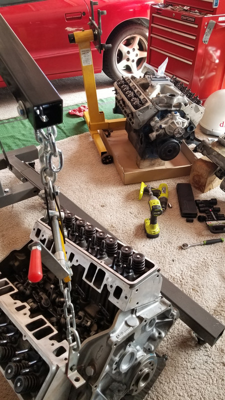
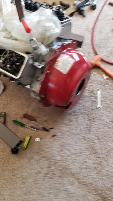
Out with the 396 and in with the 434. If one motor had a problem on a race day we could stuff the other one in that day
Bad picture because I was in a hurry to stuff the new motor in with a friend. 22 pound SFI steel fly and 800 FP of torque single disk clutch assembly


 , but so far it seems to be a guessing game for what torsional improvement is available and what the offsetting weight penalty is.


 Once you get into the 500+ hp and higher RPM you need the best SFI rated stuff everywhere. Blow proof bell housings are a must!