


Oil Catch Can Question...
Drifting


Joined: Mar 2003
Posts: 1,398
Likes: 1
From: Kingsport TN
I have a related question, not to hijack this thread though! I just installed the NLP catch can on my 99 w/ A&A Procharger unit. I hooked the pcv line into the upper fitting of the can, then connected the lower fitting to the pcv valve housing which then connects to the intake manifold.
I see two different posts on how to do this. One is the way I said above, another is to have the pcv valve upstream of the catch can before the first tube inserts into the top fitting of the can. Guess it doesn't matter much, but I'd like to see what u all think.
I found it easier to hook it up as I stated above since it's a tough 90 deg turn on the tubing if I try to hook it up w/ the pcv valve upstream of the can. That valve apparatus doesn't move much since it has the securing wire attached to the engine block.
Thanks for the input!
Le Mans Master

Joined: Dec 2003
Posts: 5,561
Likes: 448
From: Atlanta metro Ga.
Logically the location of the PCV valve in the loop should make no difference.
On another note, with your supercharged application, you have other areas of consern, but I'm no expert. Call Andy over at A&A Corvette, I'm sure he would have additional input.
On another note, with your supercharged application, you have other areas of consern, but I'm no expert. Call Andy over at A&A Corvette, I'm sure he would have additional input.
Last edited by Dan_the_C5_Man; Dec 2, 2006 at 05:22 PM.
Thread Starter
Melting Slicks


Joined: Jun 2006
Posts: 2,923
Likes: 1
From: Cleveland Tennessee
[QUOTE=berryj]I have a related question, not to hijack this thread though! I just installed the NLP catch can on my 99 w/ A&A Procharger unit. I hooked the pcv line into the upper fitting of the can, then connected the lower fitting to the pcv valve housing which then connects to the intake manifold.[QUOTE]
That sounds about right to me, and I think that I too hooked mine up that way, although I do not have the supercharger
That sounds about right to me, and I think that I too hooked mine up that way, although I do not have the supercharger
Team Owner

Joined: May 2001
Posts: 36,836
Likes: 244
From: Dear Karma, I have a list of people you missed.
St. Jude Donor '08-'09-'10-'11-'12-'13-'14-'15-'16
Originally Posted by Dirty Howie
This is a view of where it is......standing in front of the car with the hood up.
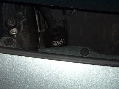
DH
DH
Same for me. Only small difference is I'm using two AMW clamps and my can is installed leaning back at about a 45 degree angle. Pretty sure Patches has his installed there too.

Robert
Melting Slicks
Joined: Oct 2006
Posts: 2,228
Likes: 5
From: Gainesville Georgia
Originally Posted by berryj
I have a related question, not to hijack this thread though! I just installed the NLP catch can on my 99 w/ A&A Procharger unit. I hooked the pcv line into the upper fitting of the can, then connected the lower fitting to the pcv valve housing which then connects to the intake manifold.
I see two different posts on how to do this. One is the way I said above, another is to have the pcv valve upstream of the catch can before the first tube inserts into the top fitting of the can. Guess it doesn't matter much, but I'd like to see what u all think.
I found it easier to hook it up as I stated above since it's a tough 90 deg turn on the tubing if I try to hook it up w/ the pcv valve upstream of the can. That valve apparatus doesn't move much since it has the securing wire attached to the engine block.
Thanks for the input!
I see two different posts on how to do this. One is the way I said above, another is to have the pcv valve upstream of the catch can before the first tube inserts into the top fitting of the can. Guess it doesn't matter much, but I'd like to see what u all think.
I found it easier to hook it up as I stated above since it's a tough 90 deg turn on the tubing if I try to hook it up w/ the pcv valve upstream of the can. That valve apparatus doesn't move much since it has the securing wire attached to the engine block.
Thanks for the input!

Race Director


Joined: Dec 2000
Posts: 19,304
Likes: 85
From: San Diego CA
Originally Posted by Dan_the_C5_Man
Dave has access to CAD/CAM and milling machines, so it looks like he made a small aluminum can to replace the small plastic / glass unit on the air compressor filter.
If I had access to the tools and machines Dave does, hell, my wife and kids would only see me twice a day, once to eat and once to (eventually) sleep.
If I had access to the tools and machines Dave does, hell, my wife and kids would only see me twice a day, once to eat and once to (eventually) sleep.
Howie, the correctly-sized filter assembly has a capacity of 1oz. My can quadruples that, so I figure I can go almost one year before having to empty the can. You are right in that it is smaller than most catch cans and I can easily design a larger diameter can. However, that would mean higher costs and fewer areas in which to mount the assembly. It looks like you drilled and tapped holes in that front cross bar that sits behind the front fascia. If not, how did you mount it? I was looking at that area this afternoon as a possible place to mount my catch can. Drilling may be tricky unless I get ahold of a right-angle drill. That steel beam seems to be fairly think.
Dave
Race Director
Joined: Dec 2000
Posts: 19,304
Likes: 85
From: San Diego CA
[QUOTE=RonVette2][QUOTE=berryj]I have a related question, not to hijack this thread though! I just installed the NLP catch can on my 99 w/ A&A Procharger unit. I hooked the pcv line into the upper fitting of the can, then connected the lower fitting to the pcv valve housing which then connects to the intake manifold.
That sounds about right to me, and I think that I too hooked mine up that way, although I do not have the supercharger
If the catch cans are set up similarly to real coalescing filters, then the upper port is the inlet side. Since the intake hose is pulling vacuum, then its hose whould go to the lower (outlet side). It all depends upon how the filtering path is set up.
That sounds about right to me, and I think that I too hooked mine up that way, although I do not have the supercharger
Drifting
Joined: Mar 2003
Posts: 1,398
Likes: 1
From: Kingsport TN
Dave, your description is how I have mine set up. The pcv tube wraps around my passenger side then inserts into the top fitting of the can. From there after the oil vapors separate, the remaining air gets sucked out via the lower fitting, then through the pcv valve, then into the intake manifold.
528, thanks for the kudos! Love Andy's kit, no problems w/ it. Now he's switched to Vortech, but same great quality.
528, thanks for the kudos! Love Andy's kit, no problems w/ it. Now he's switched to Vortech, but same great quality.
Corvette Stories
The Best of Corvette for Corvette Enthusiasts

Top 10 Most Expensive Corvettes Ever Sold on Bring A Trailer
Brett Foote
10 Things Every Corvette Owner Needs (2026 Edition)
Michael S. Palmer
8 Most "Only Corvette Owners Understand" Quirks and Problems
Pouria Savadkouei
10 Reasons the C6 Z06 is Still A Performance Benchmark After 20 Years
Joe Kucinski
How Much Horsepower Every Corvette Engine "LOST" in 1972
Joe Kucinski
Top 10 DOs and DON'Ts for Protecting Your Convertible Top!
Michael S. Palmer
Top 10 Most Explosive Corvettes Ever Made: Power-to-Weight Ratio Ranked!
Joe Kucinski
150 hp to 1,250 hp: Every Corvette Generation Compared by the Specs That Matter
Joe Kucinski
8 Coolest Corvette Pace Cars (and Replicas) of All Time
Verdad Gallardo
Thread Starter
Melting Slicks
Joined: Jun 2006
Posts: 2,923
Likes: 1
From: Cleveland Tennessee
the can is set up with a top connector that has a screen/filter under the lid that screws onto the can, then about 1/3 ways down the can there is another connector going out the side, my view of all of this was like others here: have the inlet hose from the valley pan cover go to the side of the oil catch can, once the air and oil vapors enter the can, they would have to turn 90 degrees upwards, go through the filter/screen and out the top exit. (So in my opinion the oil vapors would drop into the bottom of the can at that point before they could try to make it up through the filter and out the can.) then the exit hose goes to the PCV and into the intake manifold.
Another reason for me choosing this way was because the "Original Set-up" was rubber hose out of valley pan cover, then a "u-shaped" plastic hose, bending u-shape upwards (A "U" on its side actually)then a rubber hose again connected to the PCV which is connected to the intake. So basically... out from below the intake, curve around and up to the PCV and into the manifold. What I did was keep the same level in lines as well by lower valley pan cover hose to lower/lowest connection on can, then upper hose off can to upper PCV on intake, seemed simply to me, and the most logical.
Another reason for me choosing this way was because the "Original Set-up" was rubber hose out of valley pan cover, then a "u-shaped" plastic hose, bending u-shape upwards (A "U" on its side actually)then a rubber hose again connected to the PCV which is connected to the intake. So basically... out from below the intake, curve around and up to the PCV and into the manifold. What I did was keep the same level in lines as well by lower valley pan cover hose to lower/lowest connection on can, then upper hose off can to upper PCV on intake, seemed simply to me, and the most logical.
Team Owner


Joined: May 2004
Posts: 26,345
Likes: 232
From: SoCal
Originally Posted by Dave68
Howie, the correctly-sized filter assembly has a capacity of 1oz. My can quadruples that, so I figure I can go almost one year before having to empty the can. You are right in that it is smaller than most catch cans and I can easily design a larger diameter can. However, that would mean higher costs and fewer areas in which to mount the assembly. It looks like you drilled and tapped holes in that front cross bar that sits behind the front fascia. If not, how did you mount it? I was looking at that area this afternoon as a possible place to mount my catch can. Drilling may be tricky unless I get ahold of a right-angle drill. That steel beam seems to be fairly think.
Dave
Dave
I did not do the drilling......Andy himself installed it for me. I didn't really pay attention to what he did.....but don't remember it being problematic. But anyone who can make their own catch can undoubtabely will figure it out
Do you have any pictures or discription of the actual filtering medium you are using ?????
DH
Team Owner
Joined: May 2004
Posts: 26,345
Likes: 232
From: SoCal
Originally Posted by RonVette2
the can is set up with a top connector that has a screen/filter under the lid that screws onto the can, then about 1/3 ways down the can there is another connector going out the side, my view of all of this was like others here: have the inlet hose from the valley pan cover go to the side of the oil catch can, once the air and oil vapors enter the can, they would have to turn 90 degrees upwards, go through the filter/screen and out the top exit. (So in my opinion the oil vapors would drop into the bottom of the can at that point before they could try to make it up through the filter and out the can.) then the exit hose goes to the PCV and into the intake manifold.
Your way catches the oil vapors at the top where they will coalesce on the filter and then get sucked as oil drops into the intake.
The vapors should enter the filter at the top first, coalesce and oil drops should fall to bottom of can.
DH

Melting Slicks
Joined: Aug 2005
Posts: 3,398
Likes: 2
I think either way will work. I just drove 300 miles with it one way and another 300 miles the other way and neither one had any oil accumulated in the can and it was some very hard 600 miles of driving. My engine with 29K on it uses absolutley no noticible oil either between oil changes (7K miles) which I guess is virtually unheard of and its driven very hard.
Race Director
Joined: Dec 2000
Posts: 19,304
Likes: 85
From: San Diego CA
Howie, here is a pic of the filter element as installed into the coalescing filter. The most effective filter media for trapping airborne oil is borosilicate microfibers. Stainless steel is sometimes used in "pre-stage" particulate filters for removing bulk liquids. However, it does little to remove the oil aerosols that dominate air that is being sucked into the intake. Now, does anyone have a right-angle drill I can borrow.....?

Thread Starter
Melting Slicks
Joined: Jun 2006
Posts: 2,923
Likes: 1
From: Cleveland Tennessee
It may seem like I would do better with a different filter media, I think that the filter that is in the oil catch can that I bought it a steel looking mesh type, it would make more sense that the other filter mentioned above would be better at catching oil in its vapor (smallest form) then the steel mesh type.
I also understand the theory mentioned above about the entering can from the top and through the filter first.
I also understand the theory mentioned above about the entering can from the top and through the filter first.
Race Director
Joined: Dec 2000
Posts: 19,304
Likes: 85
From: San Diego CA
Often in industrial applications, a particulate filter is used as a prefilter to a coalescing filter, but this is primarily because compressors that do not have air dryers, tend to produce quite a bit of water as the air temp goes from hot to cool. I drove 300+ very hard miles (maybe 500 miles, overall) and found maybe .25 - .38 oz of oil in my can today. Ideally, one would have both a particulate filter to trap any bulk liquids and a coalescing filter to trap the aerosols. I'm not so sure that we need to be fanatical about this, however.
Race Director
Joined: Dec 2000
Posts: 19,304
Likes: 85
From: San Diego CA
Originally Posted by Dirty Howie
I think this way is wrong. AMW thinks this way is wrong. Elite Engineering thinks this way is wrong.
Your way catches the oil vapors at the top where they will coalesce on the filter and then get sucked as oil drops into the intake.
The vapors should enter the filter at the top first, coalesce and oil drops should fall to bottom of can.
DH
Your way catches the oil vapors at the top where they will coalesce on the filter and then get sucked as oil drops into the intake.
The vapors should enter the filter at the top first, coalesce and oil drops should fall to bottom of can.
DH

Le Mans Master
Joined: Dec 2003
Posts: 5,561
Likes: 448
From: Atlanta metro Ga.
Originally Posted by Dirty Howie
I think this way is wrong. AMW thinks this way is wrong. Elite Engineering thinks this way is wrong.
Your way catches the oil vapors at the top where they will coalesce on the filter and then get sucked as oil drops into the intake.
The vapors should enter the filter at the top first, coalesce and oil drops should fall to bottom of can.
DH
Your way catches the oil vapors at the top where they will coalesce on the filter and then get sucked as oil drops into the intake.
The vapors should enter the filter at the top first, coalesce and oil drops should fall to bottom of can.
DH
So the bottom line is I believe you'll catch more oil droplets and potentially oil vapor with allowing gravity to work for you, not against you.
Either way you route the hoses, you are 1,000% ahead of the game compared to a stock setup.
Last edited by Dan_the_C5_Man; Dec 3, 2006 at 01:16 AM.
Team Owner
Joined: May 2004
Posts: 26,345
Likes: 232
From: SoCal
Originally Posted by Dave68
Howie, here is a pic of the filter element as installed into the coalescing filter. The most effective filter media for trapping airborne oil is borosilicate microfibers. Stainless steel is sometimes used in "pre-stage" particulate filters for removing bulk liquids. However, it does little to remove the oil aerosols that dominate air that is being sucked into the intake. Now, does anyone have a right-angle drill I can borrow.....?
Thanks for the description regarding borosilcate microfibers.
I am confused looking at your pic. The while cylinder is the filter medium correct? What is the purple appendage?? Is the cylinder filled with the medium??? Does this saturate and clog easily???
I should have come on the run today so we could have compared cans/filter mediums.
Please illucidate
DH
Le Mans Master
Joined: Mar 2002
Posts: 5,955
Likes: 161
From: PNW
Originally Posted by Dan_the_C5_Man
So the bottom line is I believe you'll catch more oil droplets and potentially oil vapor with allowing gravity to work for you, not against you.
I agree with Dirty Howie though, that if the hose that sucks from the intake is on the top of the Elite or AMW catch can it is closer to the condensed oil in the mess trap, and may be more susceptible to getting carried into the intake manifold when under high vacuum conditions.
On the Elite catch can, the fitting on the side is far removed from the oil caught in the mess filter and in the bottom of the reservoir. That means any liquid oil inside the can should never be sucked out by the vacuum of the intake manifold.
Last edited by ZeeOSix; Dec 3, 2006 at 04:14 AM.
Race Director
Joined: Dec 2000
Posts: 19,304
Likes: 85
From: San Diego CA
Originally Posted by Dirty Howie
Dave
Thanks for the description regarding borosilcate microfibers.
I am confused looking at your pic. The while cylinder is the filter medium correct? What is the purple appendage?? Is the cylinder filled with the medium??? Does this saturate and clog easily???
I should have come on the run today so we could have compared cans/filter mediums.
Please illucidate
DH
The white filter is the borosilicate fiber filter. There is a black plastic piece that threads into the aluminum top, sealing against the filter. There is no appendage - that's my car in the background. The filter is a hollow cylinder through which the air passes. Will the filter get clogged? only if there is a large amount of liquid oil trying to pass through OR if there is more than a small amount of dirt and other particulates. Since the air that is passing through is somewhat clean of solid particles, I don't expect that the filter will clog anytime soon. many larger coalescing filters have built-in differential pressure indicators that change color if the DP is above a predetermined number (10 psi, I believe). If our case, we can either plumb a DP gauge in between the two hose ends or wait until our idle become rough. A quick check would be to squeeze the hose entering the intake. If the idle stays the same, the filter is clogged. If the filter is good, the idle speed should decrease, the way I see it.
Dave
Last edited by Dave68; Dec 4, 2006 at 12:03 AM.