


IMPORTANT ELECTRICAL INFORMATION (Long!)

Heel & Toe


Joined: Dec 2011
Posts: 18
Likes: 0
From: Butler, NJ
Hi Bill, I've read this post with great interest, I'm having the same issues. I have found the grounding connection in the engine compartment, and have moved a couple of wires and some of the problems have disappeared, temorarily at least. My question to you is how do u access the the connector, separating the two compnants? I don't want to break them. Thank you for all the great information. Armond

Thread Starter
Tech Contributor


Joined: Dec 1999
Posts: 32,910
Likes: 2,402
From: Anthony TX
CI 6,7,8,9,11 Vet
St. Jude Donor '08
Well,,,,,,,,,,,,,,,,,,,,,, Ive have received four request this month for the same information so its time for a ground connector tutorial:
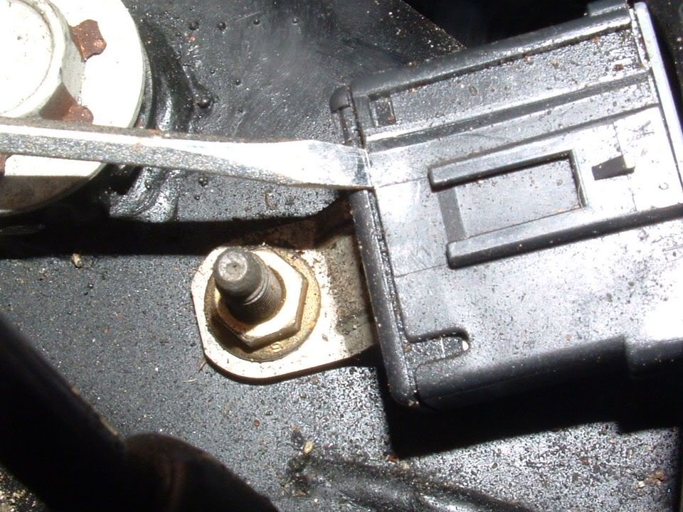
There are SIX ground connectors on the C5 Chassis like this:
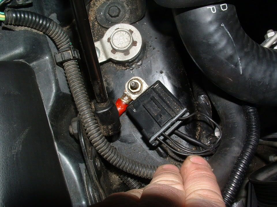
They are secured to the Chassis on a stud with a nut. The nut is 10mm and its best to use a deep well socket. There usually pretty corroded and it a very good idea to pre-soak with penetrating oil. (I use PB Blaster or Kranoil )
Once you get the nut off, this is what you will have:
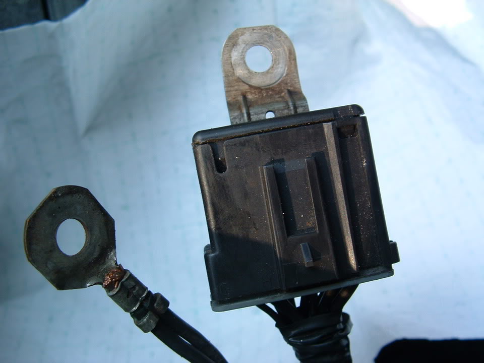
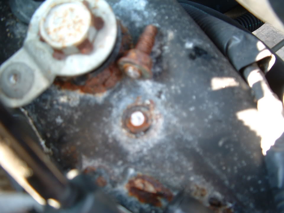
IF,,,,,,,,, this connector has corrosion, it will either be on the frame between the stud and the frame like the corrosion seen here:
Or
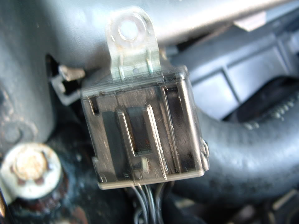
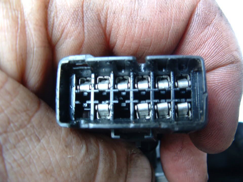
Inside the connector where you can NOT see it. To separate the connector to get to the make and female pins inside, do this:
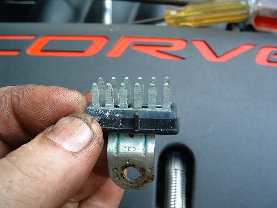
Obtain a good pair of VISE GRIPS. Attach the vise grips on the metal ground tong:
In the PLASTIC CONNECTOR BODY are TWO small plastic latches. One on EACH SIDE! Use two small flat blade screwdrivers (one on each side) to release the latches.
Grab the PLASTIC CONNECTOR BODY with your hand and the vise grip attached to the tong. PULL< WIGGLE and separate! It will be tight!!
This is what you will see when you get them apart:
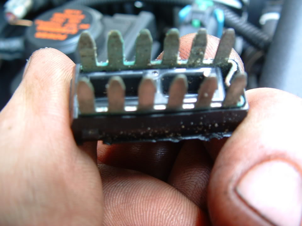
This is how corroded mine was:
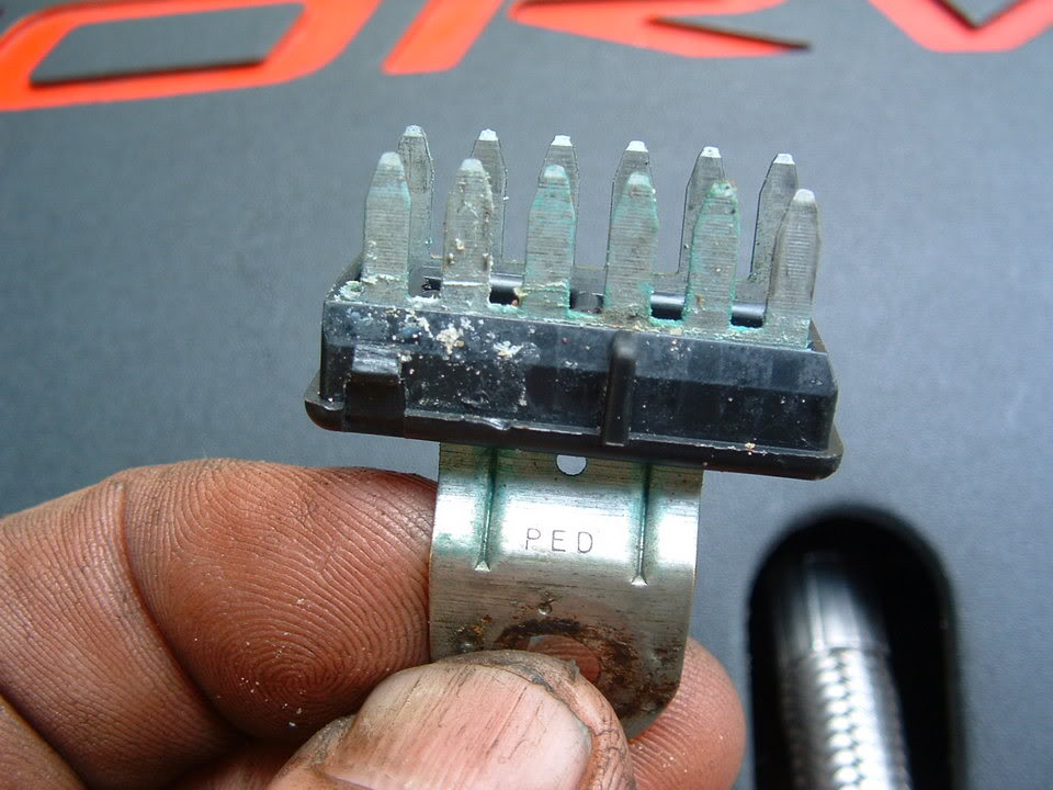
Scrub with a stainless steel or brass wire brush, flush with contact cleaner and reassemble. Make SURE that the female pins are NOT damaged or deformed. If they are, you can use a metal pick to reform the pin.
BC
There are SIX ground connectors on the C5 Chassis like this:
They are secured to the Chassis on a stud with a nut. The nut is 10mm and its best to use a deep well socket. There usually pretty corroded and it a very good idea to pre-soak with penetrating oil. (I use PB Blaster or Kranoil )
Once you get the nut off, this is what you will have:
IF,,,,,,,,, this connector has corrosion, it will either be on the frame between the stud and the frame like the corrosion seen here:
Or
Inside the connector where you can NOT see it. To separate the connector to get to the make and female pins inside, do this:
Obtain a good pair of VISE GRIPS. Attach the vise grips on the metal ground tong:
In the PLASTIC CONNECTOR BODY are TWO small plastic latches. One on EACH SIDE! Use two small flat blade screwdrivers (one on each side) to release the latches.
Grab the PLASTIC CONNECTOR BODY with your hand and the vise grip attached to the tong. PULL< WIGGLE and separate! It will be tight!!
This is what you will see when you get them apart:
This is how corroded mine was:
Scrub with a stainless steel or brass wire brush, flush with contact cleaner and reassemble. Make SURE that the female pins are NOT damaged or deformed. If they are, you can use a metal pick to reform the pin.
BC
Last edited by Bill Curlee; Mar 5, 2012 at 10:47 PM.
Heel & Toe
Joined: Dec 2011
Posts: 18
Likes: 0
From: Butler, NJ
Bill Thank you for all the great information. I've located 2 of the 6 ground connectors and followed your instructions. This seems to have solved the random stalling issues I was having, the traction control light and ABS light will light when I hit a bump which tells theres a loose connection. I will finish locating ground connectors and clean them, hopefully this will solve the problem. Thank you for all your help!!
Thread Starter
Tech Contributor
Joined: Dec 1999
Posts: 32,910
Likes: 2,402
From: Anthony TX
CI 6,7,8,9,11 Vet
St. Jude Donor '08
Please read and post all your DTCs when you have the Traction Control issues and lights/messages. Without turning the ignition off,, enter the diagnostic DTC reading routine.
Post ALL the Codes that you see.
Your issues may not be caused by a bad ground and may actually be a poor connection inside a connector. The DTC codes will help pin point the issue.
READING YOUR Engine Diagnostic Codes (DTCs)
The Diagnostic Display Mode is entered with the following procedure:
1) Turn on the ignition but don't start the engine.
2) Press the RESET button to turn off any warning messages. (i.e. door open, trunk open etc…)
3) Press and hold OPTIONS
4) While holding OPTIONS, press FUEL four times within a 10-second period.
Initially, on-board diagnostics go into an Automatic Mode which shows diagnostic codes in a pre-set sequence: PCM - TCS - RTD - BCM - IPC - RADIO - HVAC - LDCM - RDCM - SCM - RFA. All codes will be displayed for each. ( i.e. PCM = 4 codes)
If none are present in a given module, you will see No More Codes on the display.
There are two kinds of diagnostic codes, Current and History designated with a letter suffix, C or ;H. A current code indicates a malfunction is present in the module displaying data. A history code indicates a problem existed sometime in the last 40 or 50 ignition cycles. When not accompanied by a current code of the same number, it's potential evidence of a previous problem, now resolved, that was not removed by clearing the codes.
More likely it's an indication of an intermittent malfunction.
Intermittent codes are the most challenging of the diagnostics. An intermittent code may have happened once, may have happened more than once but is inconsistent or may be happening on a regular basis but not at the time the codes are displayed. History codes can also be caused by a current malfunction in a system that is not operating at the time codes are displayed. An example is the rear window defogger which doesn't operate until the Body Control Module detects engine rpm. For history codes set by a module that does not operate with the key on and engine off, a special diagnostic tool called a Scan Tester is necessary to properly diagnose the malfunction.
Once the system has displayed all modules, it goes into the manual mode which allows selection of each module using combinations of Driver Information Center buttons. Manual mode can also be entered during the automatic sequence by pressing any button except E/M. Once the display shows Manual Diagnostics, select a module by pressing the OPTIONS button to go forward or the TRIP button to go back. Once a module is selected, a code is displayed, and if more than one are present;
press GAGES to go forward or FUEL to go back.
To exit the diagnostic mode at any time, press E/M. If you want to erase codes in a given module, press RESET
To reset the codes once in manual mode, press and hold RESET until it displays NO CODES Press OPTIONS to go to the next module. Repeat the steps until you have reset the codes in all the computer modules.
NOTE!! Only reset the codes IF you want to - it is NOT necessary to do this. Clearing a code does not repair a problem. You are simply erasing the evidence of it in the module's memory. If you clear the code/s, and extinguish the Check Engine Light, your emissions status ready will NOT allow you to pass an emissions test until you have completed the required driving cycles.
Once you have the codes, the next question is: What to do with the information?
First, consult the factory service manual. Any serious C5 Do-It-Yourself owner should invest in the Corvette Service Manual of the appropriate model year. The Service Manual is really a requirement if you want to understand and work on your C5.
Here is very good site of DTC definitions:
http://www.gearchatter.com
Make sure to include the H or C suffix!!

Heel & Toe
Joined: May 2011
Posts: 19
Likes: 0
Special thanks to all that helped throughout serveral times left stranded waiting for a tow back home. I cleaned every ground on my 99 Coupe but still had the problem.
I finally discovered that after complete warm up my "CRANKSHAFT POSISTION SENSOR" was failing and ultimatly shutting down the engine. This would happen at any given time, even at 70 MPH. I really don't know of a way to diagnose the sensor problem without replacement, and none of my codes sent me directly to the sensor.
With this said, if anyone out there has this issue they might want to replace the sensor. Of coarse I broke three exhaust studs pulling the exhaust system due to the sensor being located behind the starter. I still had the project completed in six hours.(shade tree mechanic)
We now have over 1500 miles on the car since replacement and no issues to date.
Thanks and "Good Vetting" out there.
PHASTC5

Advanced
Joined: Feb 2012
Posts: 56
Likes: 2
RCDLR , horn chirps when learning TPM's but FOB will not learn. New FOB with coresponding FCC numbers P/N 10422088. Question: has anyone resoldered the chip and or other parts on the board in the RCDLR ? All wheels learn except RR., yet it shows areading on the DIC. LR shows XXXX on DIC. DIC shows service TPM system. I really don't want to spend the $400 to convert to 2000 C5 RCDLR and TPM's if a simple resoldering job will make the FOB program.

Instructor
Joined: Jan 2011
Posts: 114
Likes: 0
From: tucson az
Ok the other day i was getting my c6 a6 car tuned by my friend and he said that one of my o2's was reading weird so he reccomended that i change it out before the dyno tune. so i did so and right after the change of the new 02 sensor the 02 fuse blew so i replaced it but the horn stopped working right after that? the fuses for the horn were ok and the relay was working because it was clicking. the next day I go to get it dyno tuned and decide to worry about horn later and my dyno tune goes fine but on the way back my ewp blows a fuse 2 x's so i finaly get home and check for shorts/ground problems etc and fine none. so after the 3rd time of replacing the fuse it stops blowing and now a service electrical system comes on and the car starts constantly missfiring and wont accelerate at full power when i push on it. it just stutters and the volts read real low like 11.9 when in any gear but park, that reads 14.5 but as soon as it goes on R,D,N it starts reading under 12 every time. What is even more weird is that the accelerating problem didn't happen right away it was saying service electrical system but it would still go at full power but now it is limping and wont go fast even at full throttle. the battery and alt checked out fine on machine. i checked all grounds and wires for 12 hrs and did not find anything obvious. Can the tune have anything to do with this? Because before the car was tuned when i went to switch gears the car would almost stall out everytime and drop to as low as 200rpm but then would come back up to 900 (stroked 402ci big cam,ud pulley, full boltons,stock converter), so my tuner fixed the idling issue and it never dropped below 700rpm after the tune and he did make the only light go away which was a vaccum code but i guess that is typical from big cams. So any more ideas? Oh ya and before any of these problems happened the car did act up on once before on the throttle thing not taking off fast when gas pedal pushed to floor it happened before tune but it went back to normal on it's own after 5 minutes and didn't come back until now but with the SES.
Drifting

Joined: Nov 2011
Posts: 1,401
Likes: 141
From: Summerville South Carolina
check out today's post on "Why do I get these DIC Codes?"
A fellow member and I are pulling the exact same codes with me also having my IPC go out when I pull these codes. Had not looked at the connectors under the footwell.
Thanks, Dave
A fellow member and I are pulling the exact same codes with me also having my IPC go out when I pull these codes. Had not looked at the connectors under the footwell.
Thanks, Dave
Corvette Stories
The Best of Corvette for Corvette Enthusiasts

Top 10 Most Expensive Corvettes Ever Sold on Bring A Trailer
Brett Foote
10 Things Every Corvette Owner Needs (2026 Edition)
Michael S. Palmer
8 Most "Only Corvette Owners Understand" Quirks and Problems
Pouria Savadkouei
10 Reasons the C6 Z06 is Still A Performance Benchmark After 20 Years
Joe Kucinski
How Much Horsepower Every Corvette Engine "LOST" in 1972
Joe Kucinski
Top 10 DOs and DON'Ts for Protecting Your Convertible Top!
Michael S. Palmer
Top 10 Most Explosive Corvettes Ever Made: Power-to-Weight Ratio Ranked!
Joe Kucinski
150 hp to 1,250 hp: Every Corvette Generation Compared by the Specs That Matter
Joe Kucinski
8 Coolest Corvette Pace Cars (and Replicas) of All Time
Verdad Gallardo
Advanced
Joined: Nov 2011
Posts: 88
Likes: 0
From: DFW TX
Have a problem and was wondering what the experts think:
The turn signal will not work at times. When I initiate the turn signal, nothing will flash or click. When that happened one time, I pushed the emergency flasher button and the turn signal worked as normal. Lately, I've been doing that and it hasn't worked so I tap the dash area right above the emergency flasher button.
Any ideas on what I need to do? I'm going to have to take the dash apart, aren't I?
Which leads to me today. I use the turn signal (it worked) and it was flashing really really quick. Okay, no problem, I think, it's just a burned out bulb. It was a burned out bulb, came home from work and replaced the burned out bulb, passenger side DRL. After replacing, I initiate the turn signal and it's still flashing really really quick but the DRL is on.
What gives?
My car is a 2003 Z06, it's been 9 years but it looks like age is starting to catch up!
I'm having the same problem... Were you ever able to get this resolved?? THANKS!
Thread Starter
Tech Contributor
Joined: Dec 1999
Posts: 32,910
Likes: 2,402
From: Anthony TX
CI 6,7,8,9,11 Vet
St. Jude Donor '08
The emergency flasher module is bad. There is a way to replace it without a lot of work BUT,,,,, there is also a new flasher module/harness that you can install. Its a lot easier and works better.
BC
BC
Advanced
Joined: Nov 2011
Posts: 88
Likes: 0
From: DFW TX
Thanks for the reply. I went in an installed a new flasher module. This took care of the Hyper flash blinking in my tail lights, but my front passenger turn signal still wont wont. DRL's work and i've replaced the bulb even though the filaments looked fine. Do you think this is a problem with the turn signal socket that the bulb is housed in.. or possibly the multi function lever on the steering column?
Thanks again.
2004 Z06
Last edited by NewbieHunter; Apr 27, 2012 at 11:46 AM.
Burning Brakes

Joined: Sep 2010
Posts: 901
Likes: 1
From: LaPorte Indiana
this thread helps alot. do you happen to know which ground controls the ebcm and do you have a pic/diagram that displays it?
about a year and a half ago i got the traction service light with abs. when i shut the car off it didnt come back on for a while until recently i took my car to get the rocker panels repainted. when i got the car back i had the service traction system and this time it wont go away. the only code is c1214. i was about to pull it off (ebcm) and send it to absfixer but then started reading about cleaning ground connections first
about a year and a half ago i got the traction service light with abs. when i shut the car off it didnt come back on for a while until recently i took my car to get the rocker panels repainted. when i got the car back i had the service traction system and this time it wont go away. the only code is c1214. i was about to pull it off (ebcm) and send it to absfixer but then started reading about cleaning ground connections first
Drifting
Joined: Nov 2011
Posts: 1,401
Likes: 141
From: Summerville South Carolina
I have gone through all the grounds and busses, replaced the battery and gone over the door wiring harnesses in the accordians. Yet the IPC and HUD continue to go out from time to time and then comes back on for awhile. All guages go to 0.The IPC was replaced by the former owner at a Chevy dealer owner to no avail. Codes are all communivation codes.
Someone suggested the ignition switch. Bill, what do you think? Could it be the switch. It is an 01 with only 17.5 k on it. The switch works fine in all other respects.
Someone suggested the ignition switch. Bill, what do you think? Could it be the switch. It is an 01 with only 17.5 k on it. The switch works fine in all other respects.
Thread Starter
Tech Contributor
Joined: Dec 1999
Posts: 32,910
Likes: 2,402
From: Anthony TX
CI 6,7,8,9,11 Vet
St. Jude Donor '08
I have gone through all the grounds and busses, replaced the battery and gone over the door wiring harnesses in the accordians. Yet the IPC and HUD continue to go out from time to time and then comes back on for awhile. All guages go to 0.The IPC was replaced by the former owner at a Chevy dealer owner to no avail. Codes are all communivation codes.
Someone suggested the ignition switch. Bill, what do you think? Could it be the switch. It is an 01 with only 17.5 k on it. The switch works fine in all other respects.
Someone suggested the ignition switch. Bill, what do you think? Could it be the switch. It is an 01 with only 17.5 k on it. The switch works fine in all other respects.
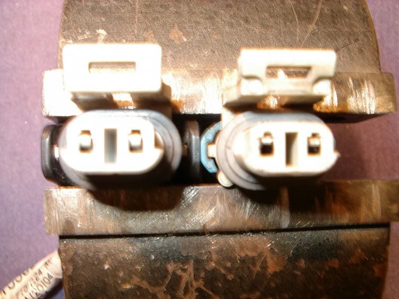
EXAMPLE:
Good on the LEFT,,, BAD on the right
You stated that you have NO COMMS codes. That could indicate that you have a power issue OR a class 2 serial buss issue. Find the FUSE or FUSES for the module and measure the fuse test points to ground (with the key on) and make sure that the voltage you see is the same as actual battery voltage. Depending on if the fuse is supplied by the battery or ignition switch will be your answer if the voltage is deficient.
Examine the DIC and see if any of the other modules has a COMMS issue. If so, you most likely have a module with a voltage issue or compromised class 2 serial buss.
Examine this post for further guidance
- C5 SERIAL DATA BUSS ISSUES: http://forums.corvetteforum.com/c5-t...-there-is.html
Drifting
Joined: Nov 2011
Posts: 1,401
Likes: 141
From: Summerville South Carolina
I'll proceed as you suggest and will recheck the connectors. Often , If I shut the ignition and engine down , and then restart the car the IPC will return to normal for awhile which is making me think IGN. switch. But, I will run the other other tests before replacing it.
Thanks again, Dave
Thanks again, Dave

Advanced
Joined: Jul 2007
Posts: 79
Likes: 0
Hey guys...had a weird issue that I emailed Bill about but thought maybe someone here had seen something similar...here it goes:
I ran into a very strange problem today driving home from work and was hoping you might have some insight into fixing it. Here is a bit of what happened:
I started the car to drive home from work and about 3 minutes into the trip, I noticed that my Turn Signal Indicators were slightly illuminated and would not turn off. Pressing the Hazard Switch would activate the Hazards as normal and the turn signals also would work, however the other signal would still stay illuminated on the dash. I shut off the car and restarted it hoping that it was a minor glitch and that may give it the reboot it needed. After driving another few minutes I noticed there were a few other symptoms which included all the lights on my dashboard and radio being on even though the lights were not turned on. At this time I looked into what codes I had and the following were displayed:
B2578 & B2583 - L/R Turn Signal
P1593 - AC Clutch Feedback
I work about 40 miles from home and at this point hoped to make it home. I kept driving and further noticed that my High Beams were slightly illuminated at all times. If I would pull the stick to flash my high beams than they would fully light up. Turning on my lights however would not turn on my lights. (FYI...I have been running HIDs for about 2 years) I also noticed that my AC would not work and was blowing out warm air so I shut the AC down.
My driving was not effected until I hit some traffic on the highway and noticed that my temps were starting to rise up to around 230/235. At this point, I realized that my fans were no longer turning on either. Traffic broke up and I was able to get the temps to around 210-220 when driving. This was fine until I hit Staten Island and hit traffic on the streets and the temps quickly got up to 240-250. At this point I knew I wasn't going to make it home during rush hour and pulled off the road and parked the car.
I tried pulling the battery for about 10 minutes with the car parked to see if that would rectify the glitch but to no prevail. I will be picking up the car later to begin trying to figure out where the issue lies. I am thinking it is one of the following:
- Dirty or loose chasis grounds?
- Bad Hazard Switch - I bypassed the hazard switch to a normal turn signal relay about 2 years ago due to having intermittent turn signal issues.
Do you think the 3 codes are related to the electrical issue or is the P1593 a separate issue? Do you have any thoughts on where I should start looking? Do you think it is the BCM....really hope not.
Another FYI...the battery was replaced about 9 months ago when I did the Steering Lock Bypass so not thinking its a bad battery but I'm guessing it could be....thoughts?
Thanks everyone...really appreciate any help or advice that can be offered for troubleshooting!!!
Instructor
Joined: Jan 2009
Posts: 140
Likes: 1
From: Whitesboro Texas
I had a similar problem a few months back. My blinkers would stay illuminated the same as yours. Hazards worked properly etc. Blinkers would blink like one of the bulbs was burner out (semi hyperflash). When I used my passive feature on the locks it would set the alarm off. What I found was a splice pack under the front bumper where the running light harnes grounds come together had a tension bar in it which was slightly bent and not making good ground contact. I pulled the splice pack apart cleaned it, made sure all of the bars were bent down, put it back together and it has given me no trouble since. I still plan to remove the splice pack and solder all of the grounds together but there has been no rush since it works fine now. Hope this helps
Rick
Rick

5th Gear
Joined: Dec 2008
Posts: 5
Likes: 0
I have a 2002 Convertible with Active Handling.
I�ve cleaned the grounds except for 201,202,301 and 302.
How do I get to these grounds?
The codes that have been coming up are
A0-LDCM2262
28-TCSC1225
Thanks for you help
I�ve cleaned the grounds except for 201,202,301 and 302.
How do I get to these grounds?
The codes that have been coming up are
A0-LDCM2262
28-TCSC1225
Thanks for you help
Thread Starter
Tech Contributor
Joined: Dec 1999
Posts: 32,910
Likes: 2,402
From: Anthony TX
CI 6,7,8,9,11 Vet
St. Jude Donor '08
LDCM
DTC B2262-B2265
Circuit Description
The driver door module (DDM) and the passenger door module (PDM) receive mirror position signals from the mirror horizontal and vertical position sensors. These signals are used by the door modules for memory recall functions of the driver and passenger mirrors. The door modules command the mirror memory settings based upon the voltage level received back from the position sensors. Each door module provides a 5 volt supply, a signal and a ground circuit for each of the position sensors. The horizontal and vertical position sensors are variable resistors that the door modules monitor voltage levels across. When a memory setting is recalled, the door modules command the mirror motors in the appropriate directions until the stored position sensor voltage levels are achieved. The DDM and PDM monitor the signal circuits to determine if the voltage level is out of range. If the DDM or PDM detects a voltage level out of range for greater than 2 seconds, a DTC is set.
Conditions for Setting the DTC
The DDM or PDM detects a mirror position sensor signal voltage range under 0.1 volts or over 4.78 volts.
Condition must be present for greater than 2 seconds.
Action Taken When the DTC Sets
Stores a history DTC B2262, B2263, B2264 or B2265 in the DDM or PDM memory.
These DTCs can only be set as a history code even if the malfunction is current.
No driver warning message will be displayed for this DTC.
Conditions for Clearing the DTC
The DDM or PDM detects the correct mirror horizontal and vertical position sensor signal voltage range (0.1-4.78 volts) for longer than 2 seconds, and:
The DTC is cleared using the IPC clearing feature, or
The DTC is cleared using a scan tool.
Diagnostic Aids
An intermittent malfunction may be caused by an intermittent open or short to ground in a mirror signal circuit.
If the DTC does not reset after the code is cleared, then the problem may be intermittent. Refer to Testing for Intermittent and Poor Connections in Wiring Systems.
Test Description
The numbers below refer to the step numbers on the diagnostic table.
This tests the mirror position sensor signal voltage using a scan tool. Normal signal voltage range is between 0.1-4.78 volts.
This tests the mirror position sensor signal voltage using a scan tool with the mirror disconnected. Normal signal voltage range with the mirror disconnected is greater than 4.78 volts.
This tests the mirror position sensor signal voltage using a scan tool with the signal circuit jumpered to the sensor ground circuit. Normal signal voltage range with the sensor jumpered to ground is less than 0.1 volt.
Step
Action
Value(s)
Yes
No
Schematic Reference: Door Control Module Schematics
Connector End View Reference: Power Door Systems Connector End Views
1
Did you perform the Door Systems Diagnostic System Check?
--
Go to Step 2
Go to Diagnostic System Check - Door Systems
2
Install a scan tool.
Turn ON the ignition, with the engine OFF.
With a scan tool, observe the appropriate mirror position parameter in the appropriate door control module data list.
Does the scan tool indicate that the mirror position parameter is within the specified range?
0.1-4.78 V
Go to Testing for Intermittent and Poor Connections in Wiring Systems
Go to Step 3
3
Turn OFF the ignition.
Disconnect the appropriate mirror.
Turn ON the ignition, with the engine OFF.
With a scan tool, observe the appropriate mirror position parameter in the appropriate door control module data list.
Does the scan tool indicate that the mirror position parameter is greater than the specified value?
4.78 V
Go to Step 4
Go to Step 5
4
Turn OFF the ignition
Connect a 3-amp fused jumper wire between the signal circuit of the appropriate mirror position sensor and the ground circuit of the appropriate mirror position sensor.
Turn ON the ignition, with the engine OFF.
With a scan tool, observe the appropriate mirror position parameter in the appropriate door control module data list.
Does the scan tool indicate that the mirror position parameter is less than the specified value?
0.1 V
Go to Step 7
Go to Step 6
5
Test the appropriate mirror position signal circuit for a short to ground. Refer to Circuit Testing and Wiring Repairs in Wiring Systems.
Did you find and correct the condition?
--
Go to Step 11
Go to Step 8
6
Test the appropriate mirror position signal circuit for a high resistance or an open. Refer to Circuit Testing and Wiring Repairs in Wiring Systems.
Did you find and correct the condition?
--
Go to Step 11
Go to Step 8
7
Inspect for poor connections at the harness connector of the appropriate mirror. Refer to Testing for Intermittent and Poor Connections and Connector Repairs in Wiring Systems.
Did you find and correct the condition?
--
Go to Step 11
Go to Step 9
8
Inspect for poor connections at the harness connector of the appropriate door module. Refer to Testing for Intermittent and Poor Connections and Connector Repairs in Wiring Systems.
Did you find and correct the condition?
--
Go to Step 11
Go to Step 10
9
Replace the appropriate mirror. Refer to Mirror Replacement .
Did you complete the replacement?
--
Go to Step 11
--
10
Replace the appropriate door module. Refer to Door Control Module Replacement .
Did you complete the replacement?
--
Go to Step 11
--
11
Use the scan tool in order to clear the DTCs.
Operate the vehicle within the Conditions for Running the DTC as specified in the supporting text.
Does the DTC reset?
--
Go to Step 2
System OK
--------------------------------------------------------------------------------
Document ID# 678706
2002 Chevrolet Corvette
Try this:
Run your mirror/s MANUALLY with manual control switch thru ALL of its positions. Make sure that you go LIMIT TO LIMIT stop several times and see if that DTC clears.
The other DTC doesnt register. Reread it and make sure that you copy it correctly. I googled it and it is
LF excessive wheel speed variation
The female connections in the jumper cable or the connector on the K , member are most likely spread apart and make poor connectionBill
Racer
Joined: Dec 2009
Posts: 357
Likes: 0
From: Pas de Calais
I get the message "coolant liquid too low" every 5 minutes. When I check the level, it is okay. I was going to order a full replacement but I then thought about checking the ground point related to this message. Could you tell me which one it is please ?
Many thanks.
PS : thanks for the very usefull post.
Many thanks.
PS : thanks for the very usefull post.