


IMPORTANT ELECTRICAL INFORMATION (Long!)
Racer

Joined: Nov 2005
Posts: 374
Likes: 0
From: Corona CA - "An Armed Society is a Polite Scociety"
Well I got to the ground connectors under the hood on the driver and passenger side. Passenger was okay but the one on the driverside had about a table spoon full of sand. No corrosion on either one but I cleaned them anyway. I may have found the problem, ya think?

Racer

Joined: Jun 2005
Posts: 261
Likes: 2
From: Old Saybrook CT
Hey Bill. I posted a while back then you had some discussion with Bill Johnson about my and his issues.
First I have cleaned the engine bay connectors and the two in the rear fender area on the frame.
I had been getting the Service Vehicle Soon DIC readout but figured it was for my hollowed out cats that I did a couple of weeks ago. However today the car did some really evil stuff..
I was on the highway with the cruise set at 72 and the cruise shut off the display read "reduced engine power" and would not allow me to keep going. It died and was coasting to a stop. I turned the key of while rolling and started it back up and got the traction control and abs errors as well as service engine soon and reduced power. I ened up comming to a stop on the side of the highway safely. I tuned the key off and took it out of the ignition before deciding I should try starting it again. It fired and i drove it home with nothing more than the service vehicle soon DIC readout. I spent a few hours tonight on the grounds but had already done all of the ones that i know about.
Any idea where this reduced engine power display comes from? In terms of what ground might cause this?
I am getting low readings on the voltage while driving at 12.8 and when i touch the brakes or the fan comes on I see a drop to as low as 11.5 sometimes. What other info do you need and do you have any idea what is causing this? The only ground that I haven't delt with was the one shown that had been covered in the battery acid. I did have that problem so it may be corroded. However is this one that could cause the problems I am having or is it a ground for the fan or something more trivial?
I am scared to drive the car now but have to because my subaru is appart getting a turbo.
Oh and I broke the passenger stud off tonight to. Then I lost a tool in the front bumper... That was frustrating. I am planning on getting rid of those connectors and soldering a circular connector soon but they are clean now and shouldn't be the problem here..
Thanks for any help and pm me if you want to call me up rather than trying to reply on this. I can write up what worked if i get it fixed with what help you can give me. Thanks,
Bret
Edit: I am not sure but the service vehicle soon readout could be for a pending rear 02 code. That would explain that but still have no idea what the car dying and giving me all of the weird redouts about abs and traction control and reduced engine power would be.. thanks
Last edited by BretCutler; Apr 27, 2006 at 02:13 PM.

Racer

Joined: Aug 2001
Posts: 250
Likes: 0
From: Clarksville MD
Originally Posted by Bill Curlee
mowrey96
There is a remote possibly that you have a wiring harness problem. On some C5's the wiring harness was a little short. Take a look at the area at the back of the engine where it comes up from the bell housing area. It will come up and it makes a 90 degree turn and shoots forward along the drivers side of the engine. The area where it bend around that bracket at the rear of the manifold can cut the harness and short some wires.. The other possibly is the female pins in the plug that plugs into the sensor is bad.
BC
Thanks for the info. Replaced the sensor and plug. Did not fix the problem. Can I just run new wire from the IAT sensor plug to the PCM? Difficult? Ridiculous? If "no" to both, where can I find a wiring diagram to figure out where to run the wires?
thanks,
scott

Thread Starter
Tech Contributor


Joined: Dec 1999
Posts: 32,910
Likes: 2,402
From: Anthony TX
CI 6,7,8,9,11 Vet
St. Jude Donor '08
Originally Posted by mowrey96
Bill
Thanks for the info. Replaced the sensor and plug. Did not fix the problem. Can I just run new wire from the IAT sensor plug to the PCM? Difficult? Ridiculous? If "no" to both, where can I find a wiring diagram to figure out where to run the wires?
thanks,
scott
Thanks for the info. Replaced the sensor and plug. Did not fix the problem. Can I just run new wire from the IAT sensor plug to the PCM? Difficult? Ridiculous? If "no" to both, where can I find a wiring diagram to figure out where to run the wires?
thanks,
scott
Before you get too far into this and start ripping out wiring, lets take a look at the signals coming from the PCM and going back to the PCM.
The IAT sensor is nothing more than a thermistor that changes resistance from the exposed air. Examine the TAN wire. Use a volt meter and measure the TAN wire voltage. It should be 5.0 VDC.
The Purple wire is the ground wire back to the PCM.
If you read the purple wire to the tan wire with an ohm meter, you should see
You can remove the plug on the PCM and ring the wires out to see if you can read from the sensor plug to the PCM Plug.
You can remove PCM plugs C1 and C2 and read C1 pin 21 to the purple wire. You should zero ohms
Then read PCM plug C2 pin 8 to the IAT tan wire. You should zero ohms
If you read the IAT sensor with an ohm meter you should see a resistance that varies with temperature.
The service manual states that you should measure PCM terminals plug C1, pin 24 to PCM plug C2, pin 24. It should read 0-5 ohms.
Please check that stuff and see what you get.
Racer
Joined: Aug 2001
Posts: 250
Likes: 0
From: Clarksville MD
Originally Posted by Bill Curlee
Scott
Before you get too far into this and start ripping out wiring, lets take a look at the signals coming from the PCM and going back to the PCM.
The IAT sensor is nothing more than a thermistor that changes resistance from the exposed air. Examine the TAN wire. Use a volt meter and measure the TAN wire voltage. It should be 5.0 VDC.
The Purple wire is the ground wire back to the PCM.
If you read the purple wire to the tan wire with an ohm meter, you should see
You can remove the plug on the PCM and ring the wires out to see if you can read from the sensor plug to the PCM Plug.
You can remove PCM plugs C1 and C2 and read C1 pin 21 to the purple wire. You should zero ohms
Then read PCM plug C2 pin 8 to the IAT tan wire. You should zero ohms
If you read the IAT sensor with an ohm meter you should see a resistance that varies with temperature.
The service manual states that you should measure PCM terminals plug C1, pin 24 to PCM plug C2, pin 24. It should read 0-5 ohms.
Please check that stuff and see what you get.
Bill,
Will do. Can you help me with the 4th paragraph "If you read the purple wire to the tan wire with an ohm meter, you should see" See what?
thanks
Thread Starter
Tech Contributor
Joined: Dec 1999
Posts: 32,910
Likes: 2,402
From: Anthony TX
CI 6,7,8,9,11 Vet
St. Jude Donor '08
Woops,,,I should have removed that line before I sent it! there isnt a value for that reading. I thought I saw it in the troubleshooting guide but it was something that can only be read on a tech II.
The rest of the info is good.
BC
The rest of the info is good.
BC

Racer
Joined: Aug 2003
Posts: 484
Likes: 1
From: Merrimack NH
Originally Posted by BrentNY
Just got back from the best A/C guy in the area. After 3 hours my blinking A/C light problem turned out to be a shorted 34 relay. It goes back to the PCM which needs to be replaced. Thought anyone with the same problem would like to know, thats the solution at least for me anyway. Thanks Bill as always for your help, at least my grounds are clean.
Thread Starter
Tech Contributor
Joined: Dec 1999
Posts: 32,910
Likes: 2,402
From: Anthony TX
CI 6,7,8,9,11 Vet
St. Jude Donor '08
Brent
Does replacing that low pressure switch require depressurizing the system or is there a valve under the switch??
Glad that your system is fixed!!
Bill Curlee
Does replacing that low pressure switch require depressurizing the system or is there a valve under the switch??
Glad that your system is fixed!!
Bill Curlee
Corvette Stories
The Best of Corvette for Corvette Enthusiasts

Top 10 Most Expensive Corvettes Ever Sold on Bring A Trailer
Brett Foote
10 Things Every Corvette Owner Needs (2026 Edition)
Michael S. Palmer
8 Most "Only Corvette Owners Understand" Quirks and Problems
Pouria Savadkouei
10 Reasons the C6 Z06 is Still A Performance Benchmark After 20 Years
Joe Kucinski
How Much Horsepower Every Corvette Engine "LOST" in 1972
Joe Kucinski
Top 10 DOs and DON'Ts for Protecting Your Convertible Top!
Michael S. Palmer
Top 10 Most Explosive Corvettes Ever Made: Power-to-Weight Ratio Ranked!
Joe Kucinski
150 hp to 1,250 hp: Every Corvette Generation Compared by the Specs That Matter
Joe Kucinski
8 Coolest Corvette Pace Cars (and Replicas) of All Time
Verdad Gallardo
Racer
Joined: Aug 2003
Posts: 484
Likes: 1
From: Merrimack NH
Originally Posted by Bill Curlee
Brent
Does replacing that low pressure switch require depressurizing the system or is there a valve under the switch??
Glad that your system is fixed!!
Bill Curlee
Does replacing that low pressure switch require depressurizing the system or is there a valve under the switch??
Glad that your system is fixed!!
Bill Curlee
Thread Starter
Tech Contributor
Joined: Dec 1999
Posts: 32,910
Likes: 2,402
From: Anthony TX
CI 6,7,8,9,11 Vet
St. Jude Donor '08
If he just unscrewed it and then replaced it,,,then there is a schreder valve under the sensor!! depressurizing the system and refilling it takes a while!! At-least an hour plus! Thanks for the cool info!!
Bill
depressurizing the system and refilling it takes a while!! At-least an hour plus! Thanks for the cool info!! Bill
Racer
Joined: Aug 2001
Posts: 250
Likes: 0
From: Clarksville MD
Originally Posted by Bill Curlee
Scott
Before you get too far into this and start ripping out wiring, lets take a look at the signals coming from the PCM and going back to the PCM.
The IAT sensor is nothing more than a thermistor that changes resistance from the exposed air. Examine the TAN wire. Use a volt meter and measure the TAN wire voltage. It should be 5.0 VDC.
The Purple wire is the ground wire back to the PCM.
If you read the purple wire to the tan wire with an ohm meter, you should see
You can remove the plug on the PCM and ring the wires out to see if you can read from the sensor plug to the PCM Plug.
You can remove PCM plugs C1 and C2 and read C1 pin 21 to the purple wire. You should zero ohms
Then read PCM plug C2 pin 8 to the IAT tan wire. You should zero ohms
If you read the IAT sensor with an ohm meter you should see a resistance that varies with temperature.
The service manual states that you should measure PCM terminals plug C1, pin 24 to PCM plug C2, pin 24. It should read 0-5 ohms.
Please check that stuff and see what you get.
Before you get too far into this and start ripping out wiring, lets take a look at the signals coming from the PCM and going back to the PCM.
The IAT sensor is nothing more than a thermistor that changes resistance from the exposed air. Examine the TAN wire. Use a volt meter and measure the TAN wire voltage. It should be 5.0 VDC.
The Purple wire is the ground wire back to the PCM.
If you read the purple wire to the tan wire with an ohm meter, you should see
You can remove the plug on the PCM and ring the wires out to see if you can read from the sensor plug to the PCM Plug.
You can remove PCM plugs C1 and C2 and read C1 pin 21 to the purple wire. You should zero ohms
Then read PCM plug C2 pin 8 to the IAT tan wire. You should zero ohms
If you read the IAT sensor with an ohm meter you should see a resistance that varies with temperature.
The service manual states that you should measure PCM terminals plug C1, pin 24 to PCM plug C2, pin 24. It should read 0-5 ohms.
Please check that stuff and see what you get.
Bill,
Pin 21 on the C1 Red plug is not purple and pin 8 on the C2 Blue plug is not tan. I have a diagram that confirms what you stated, the wires in these locations should be the colors specified.
Am I misreading the diagram or your direction?
Thanks for your continued help and sorry this saga has to continue!

Advanced
Joined: Feb 2006
Posts: 72
Likes: 0
From: Coppell TX
Bill: I communicated with u earlier in the thread - My 98 is getting Service Vehicle Soon message randomly.
I've been working the grounds & here is what I have done so far:
1. Removed battery - checked & found no corrosion.
2. Removed and cleaned the following grounds - not really any corrosion on the grounds or connectors:
G101 & connector, G102 & connector, G104, G401
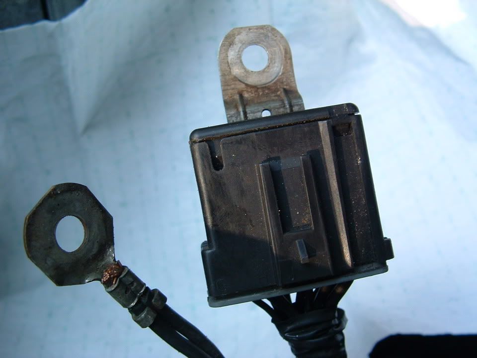
?? G402 did not have a wire connected to it & there was no wire in the vacinity. A link to pic is shown below. Is this normal??
?? Also, after reinstalling the battery & the ground cleaning, both of the key remotes stopped working.
The Service Vehicle Soon still appears randomly.
Here is a list of codes I am getting:
TCS: C1255H, C1281H
HVAC: B0363H
The following four codes are displaying for A0-LDCM, A1-RDCM & A6-SCM: U1225H, U1064H, U1016H, U1096H
Not sure how to insert a pic - here is a link to the pic of G402 which has no ground wire attached:
http://pg.photos.yahoo.com/ph/kellyh...e2.jpg&.src=ph
Any ideas on the wireless G402, remote not working & the codes?
Thanks again for sharing your expertise.
Kelly
I've been working the grounds & here is what I have done so far:
1. Removed battery - checked & found no corrosion.
2. Removed and cleaned the following grounds - not really any corrosion on the grounds or connectors:
G101 & connector, G102 & connector, G104, G401
?? G402 did not have a wire connected to it & there was no wire in the vacinity. A link to pic is shown below. Is this normal??
?? Also, after reinstalling the battery & the ground cleaning, both of the key remotes stopped working.
The Service Vehicle Soon still appears randomly.
Here is a list of codes I am getting:
TCS: C1255H, C1281H
HVAC: B0363H
The following four codes are displaying for A0-LDCM, A1-RDCM & A6-SCM: U1225H, U1064H, U1016H, U1096H
Not sure how to insert a pic - here is a link to the pic of G402 which has no ground wire attached:
http://pg.photos.yahoo.com/ph/kellyh...e2.jpg&.src=ph
Any ideas on the wireless G402, remote not working & the codes?
Thanks again for sharing your expertise.
Kelly
Thread Starter
Tech Contributor
Joined: Dec 1999
Posts: 32,910
Likes: 2,402
From: Anthony TX
CI 6,7,8,9,11 Vet
St. Jude Donor '08
Ok here ya go!
[QUOTE=Vetterable]Bill: I communicated with u earlier in the thread - My 98 is getting Service Vehicle Soon message randomly.
I've been working the grounds & here is what I have done so far:
1. Removed battery - checked & found no corrosion.
2. Removed and cleaned the following grounds - not really any corrosion on the grounds or connectors:
G101 & connector, G102 & connector, G104, G401
On G-101,102 did you completly disassemble the connector? There are 12 pins on the inside of the connector:
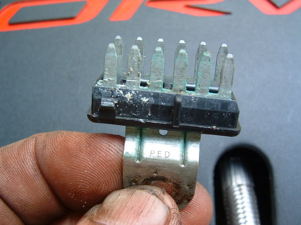
?? G402 did not have a wire connected to it & there was no wire in the vacinity. A link to pic is shown below. Is this normal??
[B][I]Depending on what year C5 you have, you may not have a wire/ground on that connector. Mid year 98 the EBTCM was moved to the front of the car and the ground was attached to G-101 via an eye;et type of ground undr the connector
?? Also, after reinstalling the battery & the ground cleaning, both of the key remotes stopped working.
As for the FOB's, there are two things that you can do:
First is a re-sync procedure. Press and hold the LOCK & UN-LOCK buttons on the FOB at the same time. Hold them until the horn toots. Then try the fob. It should work. IF it doesnt,,,,you will need to do a FOB Training sequence:
C5 FOB TRAINING PROCEDURE
Fob programming
1-Turn the ignition to RUN
2-Turn the radio off
3-Press the RESET button in order to clear any IPC warning messages
4-Press the Option button on the DIC until the IPC display is blank in order to enter the program mode
5-Press and hold the Reset button for 3 seconds
6-Press the option button until FOB Training message is displayed
7-Press the Reset button in order to begin the programming sequence.
8-Simultaneously press and hold the lock an unlock buttons on the first transmitter for 12 seconds. The IPC will indicate when that transmitter is programmed and when to proceed to the next .Repeat this step for each transmitter.
To insert a picture, your going to need to subscribe to some photo hosting service. I use www.photobucket.com It is FREE and works very well. Once you save your photos on photobucket, all you do is copy the file name and paste it into the forum post!! If I can figure it out,,,,,,Im sure you can!!!!!! Im a keeg. That 180 degrees out from a geek. Thats how easy it is!!
The Service Vehicle Soon still appears randomly.
Here is a list of codes I am getting:
TCS: C1255H, C1281H
HVAC: B0363H
The following four codes are displaying for A0-LDCM, A1-RDCM & A6-SCM: U1225H, U1064H, U1016H, U1096H
Originally Posted by Vetterable
Bill: I communicated with u earlier in the thread - My 98 is getting Service Vehicle Soon message randomly.
I've been working the grounds & here is what I have done so far:
1. Removed battery - checked & found no corrosion.
2. Removed and cleaned the following grounds - not really any corrosion on the grounds or connectors:
G101 & connector, G102 & connector, G104, G401
On G-101,102 did you completly disassemble the connector? There are 12 pins on the inside of the connector:
?? G402 did not have a wire connected to it & there was no wire in the vacinity. A link to pic is shown below. Is this normal??
Depending on what year C5 you have, you may not have a wire/ground on that connector. Mid year 98 the EBTCM was moved to the front of the car and the ground was attached to G-101 via an eye;et type of ground undr the connector:
?? Also, after reinstalling the battery & the ground cleaning, both of the key remotes stopped working.
As for the FOB's, there are two things that you can do:
First is a re-sync procedure. Press and hold the LOCK & UN-LOCK buttons on the FOB at the same time. Hold them until the horn toots. Then try the fob. It should work. IF it doesnt,,,,you will need to do a FOB Training sequence:
C5 FOB TRAINING PROCEDURE
Fob programming
1-Turn the ignition to RUN
2-Turn the radio off
3-Press the RESET button in order to clear any IPC warning messages
4-Press the Option button on the DIC until the IPC display is blank in order to enter the program mode
5-Press and hold the Reset button for 3 seconds
6-Press the option button until FOB Training message is displayed
7-Press the Reset button in order to begin the programming sequence.
8-Simultaneously press and hold the lock an unlock buttons on the first transmitter for 12 seconds. The IPC will indicate when that transmitter is programmed and when to proceed to the next .Repeat this step for each transmitter.
To insert a picture, your going to need to subscribe to some photo hosting service. I use www.photobucket.com It is FREE and works very well. Once you save your photos on photobucket, all you do is copy the file name and paste it into the forum post!! If I can figure it out,,,,,,Im sure you can!!!!!! Im a keeg. That 180 degrees out from a geek. Thats how easy it is!!
The Service Vehicle Soon still appears randomly.
Here is a list of codes I am getting:
TCS: C1255H, C1281H
HVAC: B0363H
The following four codes are displaying for A0-LDCM, A1-RDCM & A6-SCM: U1225H, U1064H, U1016H, U1096H
Ok,,your getting a LOT of "U" series codes! That usualy indicates some sort od power issue (like a low or bad battery) Remove the battery and take it to a place (Auto Zone, Advance, NAPA) that can analize your battery and see if it is good or bad. Make sure that they check for COLD CRANKING CURRENT AND VOLTAGE!!! When you crank your car the voltage has a tendancy to go low!!! If the battery is bad, it will go really low and cause you lots of unnecessary headaches and codes that really dont indicate that you have a real problem!! Get that battery checked out. Clear all of the codes once you get a good battery, CLEAR ALL OF THE CODES and then see what codes pop up!!
Not sure how to insert a pic - here is a link to the pic of G402 which has no ground wire attached:
http://pg.photos.yahoo.com/ph/kellyh...e2.jpg&.src=ph
Any ideas on the wireless G402, remote not working & the codes?
Thanks again for sharing your expertise.
Kelly
I've been working the grounds & here is what I have done so far:
1. Removed battery - checked & found no corrosion.
2. Removed and cleaned the following grounds - not really any corrosion on the grounds or connectors:
G101 & connector, G102 & connector, G104, G401
On G-101,102 did you completly disassemble the connector? There are 12 pins on the inside of the connector:
?? G402 did not have a wire connected to it & there was no wire in the vacinity. A link to pic is shown below. Is this normal??
Depending on what year C5 you have, you may not have a wire/ground on that connector. Mid year 98 the EBTCM was moved to the front of the car and the ground was attached to G-101 via an eye;et type of ground undr the connector:
?? Also, after reinstalling the battery & the ground cleaning, both of the key remotes stopped working.
As for the FOB's, there are two things that you can do:
First is a re-sync procedure. Press and hold the LOCK & UN-LOCK buttons on the FOB at the same time. Hold them until the horn toots. Then try the fob. It should work. IF it doesnt,,,,you will need to do a FOB Training sequence:
C5 FOB TRAINING PROCEDURE
Fob programming
1-Turn the ignition to RUN
2-Turn the radio off
3-Press the RESET button in order to clear any IPC warning messages
4-Press the Option button on the DIC until the IPC display is blank in order to enter the program mode
5-Press and hold the Reset button for 3 seconds
6-Press the option button until FOB Training message is displayed
7-Press the Reset button in order to begin the programming sequence.
8-Simultaneously press and hold the lock an unlock buttons on the first transmitter for 12 seconds. The IPC will indicate when that transmitter is programmed and when to proceed to the next .Repeat this step for each transmitter.
To insert a picture, your going to need to subscribe to some photo hosting service. I use www.photobucket.com It is FREE and works very well. Once you save your photos on photobucket, all you do is copy the file name and paste it into the forum post!!
If I can figure it out,,,,,,Im sure you can!!!!!! Im a keeg. That 180 degrees out from a geek. Thats how easy it is!! The Service Vehicle Soon still appears randomly.
Here is a list of codes I am getting:
TCS: C1255H, C1281H
HVAC: B0363H
The following four codes are displaying for A0-LDCM, A1-RDCM & A6-SCM: U1225H, U1064H, U1016H, U1096H
Ok,,your getting a LOT of "U" series codes! That usualy indicates some sort od power issue (like a low or bad battery) Remove the battery and take it to a place (Auto Zone, Advance, NAPA) that can analize your battery and see if it is good or bad. Make sure that they check for COLD CRANKING CURRENT AND VOLTAGE!!! When you crank your car the voltage has a tendancy to go low!!! If the battery is bad, it will go really low and cause you lots of unnecessary headaches and codes that really dont indicate that you have a real problem!! Get that battery checked out. Clear all of the codes once you get a good battery, CLEAR ALL OF THE CODES and then see what codes pop up!!
Not sure how to insert a pic - here is a link to the pic of G402 which has no ground wire attached:
http://pg.photos.yahoo.com/ph/kellyh...e2.jpg&.src=ph
Any ideas on the wireless G402, remote not working & the codes?
Thanks again for sharing your expertise.
Kelly
I've been working the grounds & here is what I have done so far:
1. Removed battery - checked & found no corrosion.
2. Removed and cleaned the following grounds - not really any corrosion on the grounds or connectors:
G101 & connector, G102 & connector, G104, G401
On G-101,102 did you completly disassemble the connector? There are 12 pins on the inside of the connector:
?? G402 did not have a wire connected to it & there was no wire in the vacinity. A link to pic is shown below. Is this normal??
[B][I]Depending on what year C5 you have, you may not have a wire/ground on that connector. Mid year 98 the EBTCM was moved to the front of the car and the ground was attached to G-101 via an eye;et type of ground undr the connector
?? Also, after reinstalling the battery & the ground cleaning, both of the key remotes stopped working.
As for the FOB's, there are two things that you can do:
First is a re-sync procedure. Press and hold the LOCK & UN-LOCK buttons on the FOB at the same time. Hold them until the horn toots. Then try the fob. It should work. IF it doesnt,,,,you will need to do a FOB Training sequence:
C5 FOB TRAINING PROCEDURE
Fob programming
1-Turn the ignition to RUN
2-Turn the radio off
3-Press the RESET button in order to clear any IPC warning messages
4-Press the Option button on the DIC until the IPC display is blank in order to enter the program mode
5-Press and hold the Reset button for 3 seconds
6-Press the option button until FOB Training message is displayed
7-Press the Reset button in order to begin the programming sequence.
8-Simultaneously press and hold the lock an unlock buttons on the first transmitter for 12 seconds. The IPC will indicate when that transmitter is programmed and when to proceed to the next .Repeat this step for each transmitter.
To insert a picture, your going to need to subscribe to some photo hosting service. I use www.photobucket.com It is FREE and works very well. Once you save your photos on photobucket, all you do is copy the file name and paste it into the forum post!!
If I can figure it out,,,,,,Im sure you can!!!!!! Im a keeg. That 180 degrees out from a geek. Thats how easy it is!! The Service Vehicle Soon still appears randomly.
Here is a list of codes I am getting:
TCS: C1255H, C1281H
HVAC: B0363H
The following four codes are displaying for A0-LDCM, A1-RDCM & A6-SCM: U1225H, U1064H, U1016H, U1096H

Melting Slicks

Joined: Feb 2002
Posts: 2,148
Likes: 1
From: GA
Originally Posted by turboed
i have a big draw,it will eat up my optima battery in about 24 hours or less,the battery is a month old and when i first put it in it sat like 3 days without a problem starting,i will check the grounds but i don't think that's the problem,anyone else have battery drain problems?

Pro


Joined: Apr 2006
Posts: 534
Likes: 82
From: Charlotte NC
Bill, I just picked up my 98 the other day and I'm trying to sort out a few problems, hopefully you can help. I Just read all 11 pages. I'm going to clean all the grounds when it stops raining.
I'm getting these codes:
PCM O2 bank 2 sensor 1:
P0153
P0154
P1153
HVAC (Dual climate control):
B0332
B0361
B0441
TCS
C1286
BO-RFA
U1096
U1064
U1016
C2120
My fob wasn't working but the lock + unlock method corrected that.
The Outside temp reading is stuck at 68* (new sensor did not fix problem)
I can adjust fan speed on the HVAC, but it only blows hot air.
Any suggestion on where to start?
Thread Starter
Tech Contributor
Joined: Dec 1999
Posts: 32,910
Likes: 2,402
From: Anthony TX
CI 6,7,8,9,11 Vet
St. Jude Donor '08
Please clear all the DTC Codes. Then start and drive the car and see if any come back. Please include if they are H history codes or C current codes.
If resttting the codes doesnt correct the problems with your HVAC, try pulling fuses # 18 and 27 in the instrument Panel fuse block in the passengers foot well.
Let me know how that works.
Bill
If resttting the codes doesnt correct the problems with your HVAC, try pulling fuses # 18 and 27 in the instrument Panel fuse block in the passengers foot well.
Let me know how that works.
Bill
Racer
Joined: Aug 2001
Posts: 250
Likes: 0
From: Clarksville MD
Originally Posted by Bill Curlee
Scott
Before you get too far into this and start ripping out wiring, lets take a look at the signals coming from the PCM and going back to the PCM.
The IAT sensor is nothing more than a thermistor that changes resistance from the exposed air. Examine the TAN wire. Use a volt meter and measure the TAN wire voltage. It should be 5.0 VDC.
The Purple wire is the ground wire back to the PCM.
If you read the purple wire to the tan wire with an ohm meter, you should see
You can remove the plug on the PCM and ring the wires out to see if you can read from the sensor plug to the PCM Plug.
You can remove PCM plugs C1 and C2 and read C1 pin 21 to the purple wire. You should zero ohms
Then read PCM plug C2 pin 8 to the IAT tan wire. You should zero ohms
If you read the IAT sensor with an ohm meter you should see a resistance that varies with temperature.
The service manual states that you should measure PCM terminals plug C1, pin 24 to PCM plug C2, pin 24. It should read 0-5 ohms.
Please check that stuff and see what you get.
Before you get too far into this and start ripping out wiring, lets take a look at the signals coming from the PCM and going back to the PCM.
The IAT sensor is nothing more than a thermistor that changes resistance from the exposed air. Examine the TAN wire. Use a volt meter and measure the TAN wire voltage. It should be 5.0 VDC.
The Purple wire is the ground wire back to the PCM.
If you read the purple wire to the tan wire with an ohm meter, you should see
You can remove the plug on the PCM and ring the wires out to see if you can read from the sensor plug to the PCM Plug.
You can remove PCM plugs C1 and C2 and read C1 pin 21 to the purple wire. You should zero ohms
Then read PCM plug C2 pin 8 to the IAT tan wire. You should zero ohms
If you read the IAT sensor with an ohm meter you should see a resistance that varies with temperature.
The service manual states that you should measure PCM terminals plug C1, pin 24 to PCM plug C2, pin 24. It should read 0-5 ohms.
Please check that stuff and see what you get.
Bill,
If the wiring diagram call for 0.350 wire, what gauge wire does that refer to? Is the length of the wire relevant when measuring resistance?
thanks AGAIN!

3rd Gear
Joined: May 2006
Posts: 3
Likes: 0
Originally Posted by mowrey96
Bill,
If the wiring diagram call for 0.350 wire, what gauge wire does that refer to? Is the length of the wire relevant when measuring resistance?
If the wiring diagram call for 0.350 wire, what gauge wire does that refer to? Is the length of the wire relevant when measuring resistance?

0.35 mm2 wire is also known as 22 gauge. I think 0.35 mm2 is cross sectional area of the wire strands.
similiarly..
0.50 mm2 = 20 gauge
0.80 mm2 = 18 gauge
1.0 mm2 = 16 gauge
2.0 mm2 = 14 gauge
3.0 mm2 = 12 gauge
5.0 mm2 = 10 gauge
etc. those are the most common SAE size wires used.
Length of wire is definitely a factor in calculating resistance. Each wire gauge has a resistance per meter value. You multiply that by the length of wire to get expected resistance of wire.
I think that 0.35 mm2 wire is typically about 52 milliohm/meter
Last edited by e2helper; May 12, 2006 at 10:03 PM.
Racer
Joined: Aug 2001
Posts: 250
Likes: 0
From: Clarksville MD
Originally Posted by e2helper
I'll try to answer that one
0.35 mm2 wire is also known as 22 gauge. I think 0.35 mm2 is cross sectional area of the wire strands.
similiarly..
0.50 mm2 = 20 gauge
0.80 mm2 = 18 gauge
1.0 mm2 = 16 gauge
2.0 mm2 = 14 gauge
3.0 mm2 = 12 gauge
5.0 mm2 = 10 gauge
etc. those are the most common SAE size wires used.
Length of wire is definitely a factor in calculating resistance. Each wire gauge has a resistance per meter value. You multiply that by the length of wire to get expected resistance of wire.
I think that 0.35 mm2 wire is typically about 52 milliohm/meter
Great info. Thanx.
I am re-wiring the IAT sensor. I had added a couple of extra feet of wire just in case. When I went for a drive I got the "active handling warming" message. I cut a few feet out of the wire and re-connected and no more message.
I still have intermittent backfire. The initial diagnosis was IAT sensor because of that error code and a laptop hooked up to the car showed dramatic temp drops at the IAT sensor when the backfiring occurred. (sensor and plug were both replaced)
Based on the original information I had I ran an 18 Gauge wire instead of 22 gauge. Can this be hampering an accurate resistance reading at the PCM like the extra length of wire was?
