


IMPORTANT ELECTRICAL INFORMATION (Long!)

Thread Starter
Tech Contributor


Joined: Dec 1999
Posts: 32,910
Likes: 2,402
From: Anthony TX
CI 6,7,8,9,11 Vet
St. Jude Donor '08
If one is bad, the other one isnt far behind so check BOTH door six pin connectors!!


Intermediate

Joined: May 2017
Posts: 30
Likes: 0
Bill Curlee, been having ongoing issues with 01 starting again!! So my ?is after messing with the starter an banging on it while my wife held the key down I got in the car and slowly kept moving the key back an forth!! And figured a way to start it but wanting to know what pieces of the switch do I replace now? I already put the Big plastic assembly part on that holds the tumbler but should I replace the keys and tumbler or just get all New switch parts all New again?? Help!! Thanks again for your expertise in all of this !! Upsman!!
Thread Starter
Tech Contributor
Joined: Dec 1999
Posts: 32,910
Likes: 2,402
From: Anthony TX
CI 6,7,8,9,11 Vet
St. Jude Donor '08
Bill Curlee, been having ongoing issues with 01 starting again!! So my ?is after messing with the starter an banging on it while my wife held the key down I got in the car and slowly kept moving the key back an forth!! And figured a way to start it but wanting to know what pieces of the switch do I replace now? I already put the Big plastic assembly part on that holds the tumbler but should I replace the keys and tumbler or just get all New switch parts all New again?? Help!! Thanks again for your expertise in all of this !! Upsman!!
The actual SWITCH Portion
The Key/Tumbler assy
The VATs sensor (on the end of the Key Tumbler )
When the car will not CRANK, is the SECURITY LIGHT in the IPC OFF or is it ON or FLASHING?????
If the VATs sensor is working and sending the key resistor value to the BCM, the VATs sensor is working.
The Tumbler has nothing to do with turning on the starter other than allowing you to actually turn the switch cause it is UN-LOCKED.
The key tumbler assy fits into a slot inside the switch and that is what turns the actual switch:

SO,,,,,, Do not replace the key tumbler if properly unlocks with the key and rotates when you turn the key.
You really need to dig out a meter and see if you have a properly operating Theft Dererrent Relay and it actually functions when you turn the key to crank.
Bill
Thread Starter
Tech Contributor
Joined: Dec 1999
Posts: 32,910
Likes: 2,402
From: Anthony TX
CI 6,7,8,9,11 Vet
St. Jude Donor '08
Corvette Stories
The Best of Corvette for Corvette Enthusiasts

Top 10 Most Expensive Corvettes Ever Sold on Bring A Trailer
Brett Foote
10 Things Every Corvette Owner Needs (2026 Edition)
Michael S. Palmer
8 Most "Only Corvette Owners Understand" Quirks and Problems
Pouria Savadkouei
10 Reasons the C6 Z06 is Still A Performance Benchmark After 20 Years
Joe Kucinski
How Much Horsepower Every Corvette Engine "LOST" in 1972
Joe Kucinski
Top 10 DOs and DON'Ts for Protecting Your Convertible Top!
Michael S. Palmer
Top 10 Most Explosive Corvettes Ever Made: Power-to-Weight Ratio Ranked!
Joe Kucinski
150 hp to 1,250 hp: Every Corvette Generation Compared by the Specs That Matter
Joe Kucinski
8 Coolest Corvette Pace Cars (and Replicas) of All Time
Verdad Gallardo
Thread Starter
Tech Contributor
Joined: Dec 1999
Posts: 32,910
Likes: 2,402
From: Anthony TX
CI 6,7,8,9,11 Vet
St. Jude Donor '08
Bill,
I wanted to use my first post to thank you. I just bought my '01 Z06 in August. It is bone stock, has been garage kept its entire life and has just over 48,600 miles, and 6,000 of those miles are mine. It also ran a 13.52@110.11MPH at Firebird Raceway in September.
My dash lights and headlights have been flickering, since I bought it, and it finally got to the point where it was bugging me last night, so a quick Google search led me to your thread. When I disconnected both grounds, only two of the pins on each connector had slight blackened corrosion on them. After using some sandpaper and electrical cleaner, I reassembled everything and took it out for a test drive; no more flickering!!!!
Thank you so much, I can't tell you how much I appreciate it.
Fred
Retired Army Guy
2001 Z06
 No problem my friend!
Bill
Retired Navy Guy

Burning Brakes


Joined: Nov 2006
Posts: 768
Likes: 25
From: Cape Cod
Hey bill,great write up on the c5 notorious electrical problems, Need a bit help here,just last summer I noticed that every time I turn the traction control off my c5 the car at times will go into limp mode, REDUCE ENGIE POWER....TRACTION CONTROL FAILURE,in the beginning it wasn't too bad, I would just shut it off wait a couple seconds and off I go,late in the summer it progressively got so bad that every time I turned the traction control of it would go into limp mode and stay there to the point that I couldn't start it back up a gain for a hour or soo,now I'm at the point that I can't take the traction control off and that's no fun.anything more I should be looking at said the grounds?.
Thread Starter
Tech Contributor
Joined: Dec 1999
Posts: 32,910
Likes: 2,402
From: Anthony TX
CI 6,7,8,9,11 Vet
St. Jude Donor '08
Hey bill,great write up on the c5 notorious electrical problems, Need a bit help here,just last summer I noticed that every time I turn the traction control off my c5 the car at times will go into limp mode, REDUCE ENGIE POWER....TRACTION CONTROL FAILURE,in the beginning it wasn't too bad, I would just shut it off wait a couple seconds and off I go,late in the summer it progressively got so bad that every time I turned the traction control of it would go into limp mode and stay there to the point that I couldn't start it back up a gain for a hour or soo,now I'm at the point that I can't take the traction control off and that's no fun.anything more I should be looking at said the grounds?.
Lets start with a good fresh DTC read using the IPC DIC.
Erase/clear "ALL" the old DTCs. Then take the car for a drive and make it fail.
When it fails, press RESET/ CLEAR to get rid of all the messages/warnings. When there all gone, read and post ALL the DTCs "BEFORE" you turn the ignition off.
Make sure that you include all the prefixis and H/Cs
With that data, we can get to troubleshooting.
Bill
Racer
Joined: Jan 2018
Posts: 249
Likes: 49
From: Westcliffe CO
Interesting old post., thanks.
My question is regarding the pronged type plugs ... How exactly were they cleaned, using what as a cleaner?
Would packing them with dielectric grease help when reassembling?
My question is regarding the pronged type plugs ... How exactly were they cleaned, using what as a cleaner?
Would packing them with dielectric grease help when reassembling?
Thread Starter
Tech Contributor
Joined: Dec 1999
Posts: 32,910
Likes: 2,402
From: Anthony TX
CI 6,7,8,9,11 Vet
St. Jude Donor '08
 Dielectric Grease is an INSULATOR!!!!!!!!!!!
If you have a BRAND NEW 100% perfect connector with 100% tight male /female pins, having grease inside the plug most likely will NOT cause any issues.
HOWEVER,,,,,,,,,,,,,,,,,,,,,,
 ,,,,,,,,,,,,,,, If you already have a compromised male female pin connection, dielectric grease could contribute or cause more electrical issues.
Do a pin PUSH /PULL test and see if there is a FIRM grip between the male and female pin. If not, find a way to correct that issue first!
Bill

4th Gear
Joined: Dec 2017
Posts: 4
Likes: 0
Im in the process of doing all the grounds and some other general maintenance on an 03 vert for a friend of mine. Ive read the entire thread and probably should have taken notes. I remember reading about a connector to check for corrosion behind the front bumper. If this is correct how do i access that one? Does the bumper have to come off the car to get to it? By the way great thread, and thanks for all the effort youve put into this stuff.
Thanks
Thanks
Thread Starter
Tech Contributor
Joined: Dec 1999
Posts: 32,910
Likes: 2,402
From: Anthony TX
CI 6,7,8,9,11 Vet
St. Jude Donor '08
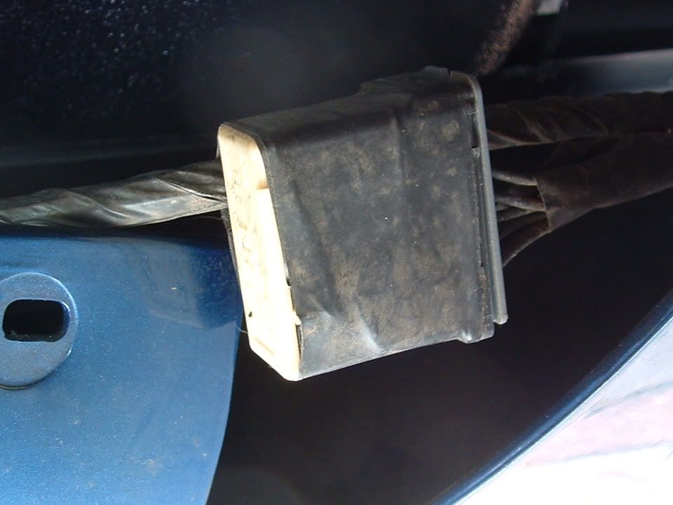
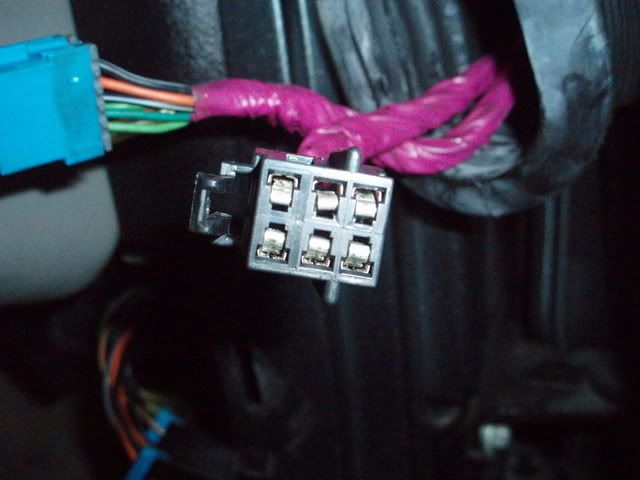
The connector that you are discussing is called a SPLICE PACK (SP). It joins common/neg wires circuits in that area. Its nothing more than a ground connector without the ground lug.
Splice Packs are normally taped to a wiring harness. The one in the bumper area can be accessed by removing the small left & right facia close out panels under the bumper. You can access it easily.
ACTUAL FRONT FACIA SPLICE PACK:
Splice Packs are normally taped to a wiring harness. The one in the bumper area can be accessed by removing the small left & right facia close out panels under the bumper. You can access it easily.
ACTUAL FRONT FACIA SPLICE PACK:
Last edited by Bill Curlee; Feb 7, 2018 at 10:29 AM.
Thread Starter
Tech Contributor
Joined: Dec 1999
Posts: 32,910
Likes: 2,402
From: Anthony TX
CI 6,7,8,9,11 Vet
St. Jude Donor '08
ABSOFRIGGENLOOTLY!!!! A Splice Pack is nothing More than a ground termination point for multiple electrical components in that area. ALL the ground wires connect in that SP and a singe wire carries the SP ground to a chassis ground point.
If ANY connector is exposed to water, salt, or a corrosive enviorment, the connections inside the connector will corrode and cause a poor ground connection.
Here is a picture/s of a chassis ground (G-101 ) and a SP that was exposed to poor environments. The corrosion rendered the grounds to a failed condition:
Exposed to North East weather:
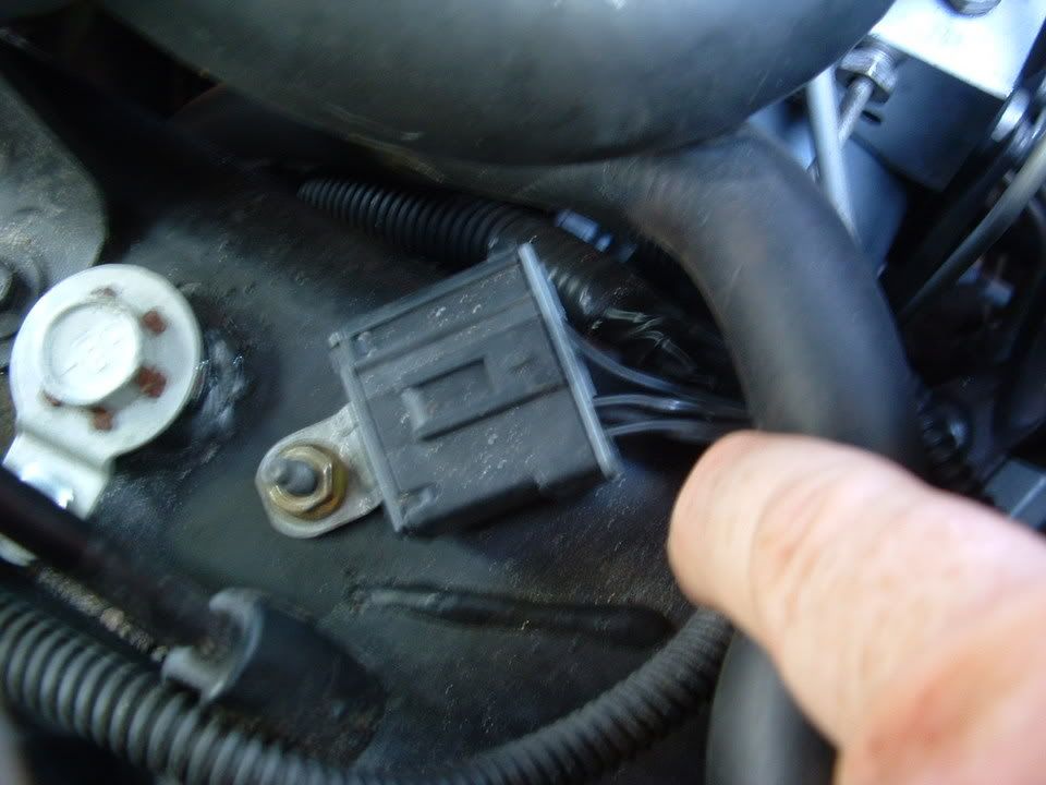
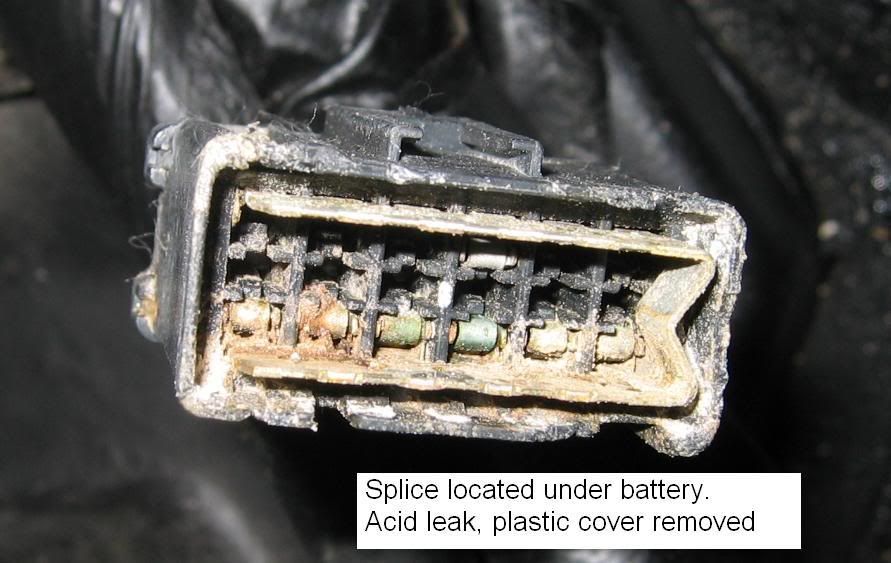
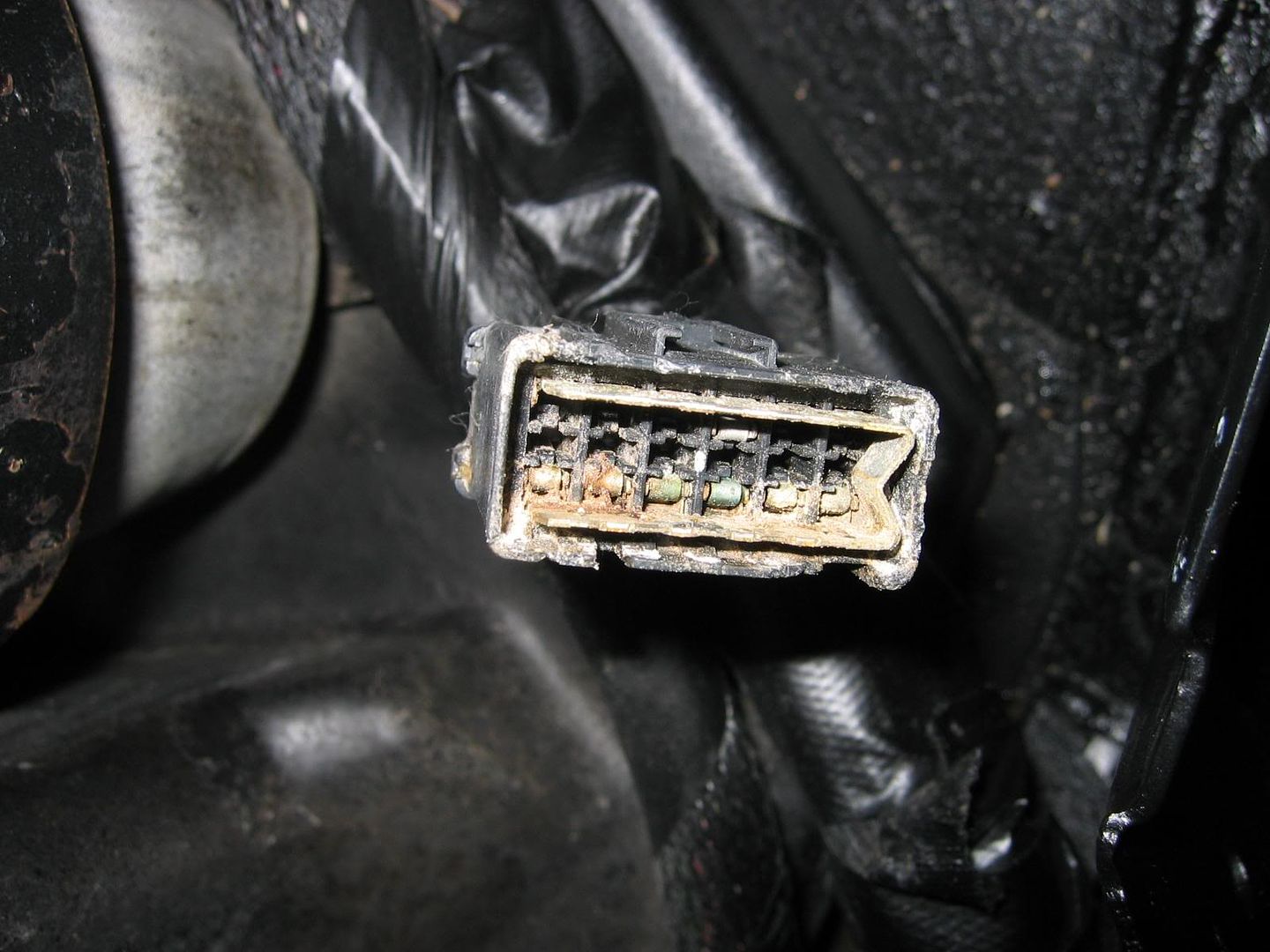
Exposed to a Leakey OEM Battery. Just the acid fumes caused this:
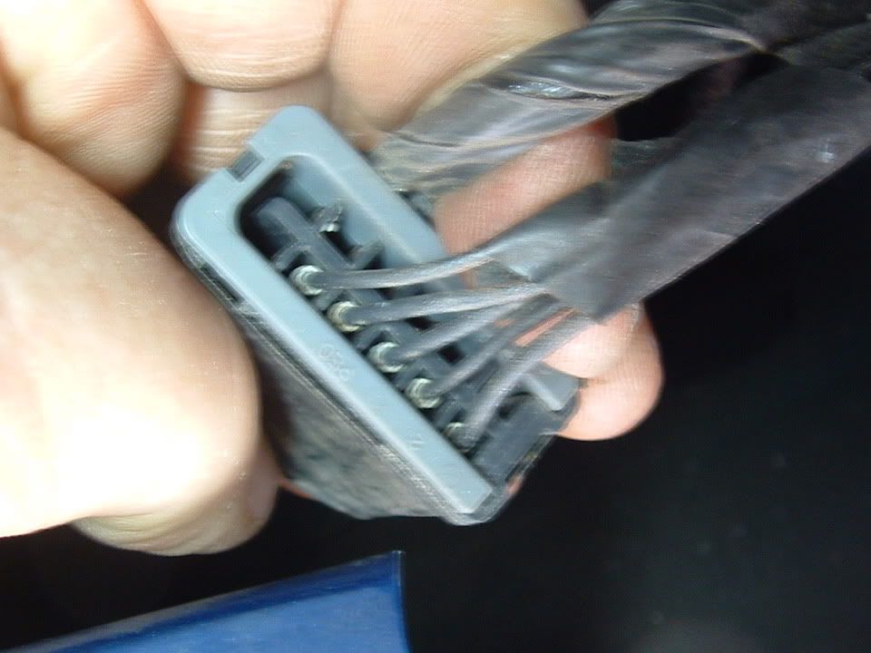
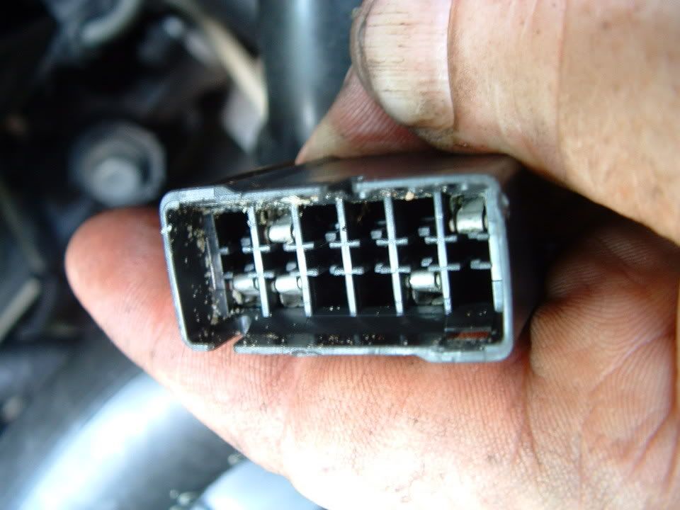
The female pins can just spread apart due to temp and vibration over time and cause a very poor connection with the MALE PIN. Very common problem with GM female pins:
Example of a really BAD female pin that had a very poor connection in a door power connector: (top row center pin is really spread apart):
A splice Pack connector is NOT water tight and always exposed to the environment.
Bill
Last edited by Bill Curlee; Feb 9, 2018 at 06:26 PM.
Burning Brakes
Joined: Nov 2006
Posts: 768
Likes: 25
From: Cape Cod
ABSOFRIGGENLOOTLY!!!! A Splice Pack is nothing More than a ground termination point for multiple electrical components in that area. ALL the ground wires connect in that SP and a singe wire carries the SP ground to a chassis ground point.
If ANY connector is exposed to water, salt, or a corrosive enviorment, the connections inside the connector will corrode and cause a poor ground connection.
Here is a picture/s of a chassis ground (G-101 ) and a SP that was exposed to poor environments. The corrosion rendered the grounds to a failed condition:
Exposed to North East weather:
Exposed to a Leakey OEM Battery. Just the acid fumes caused this:
The female pins can just spread apart due to temp and vibration over time and cause a very poor connection with the MALE PIN. Very common problem with GM female pins:
Example of a really BAD female pin that had a very poor connection in a door power connector: (top row center pin is really spread apart):
A splice Pack connector is NOT water tight and always exposed to the environment.
Bill
Thread Starter
Tech Contributor
Joined: Dec 1999
Posts: 32,910
Likes: 2,402
From: Anthony TX
CI 6,7,8,9,11 Vet
St. Jude Donor '08
So, If you have six wires in one SP, five of them will be circuit negitive wires and one will connect all the rest to a specific chassis ground lug.
SO,,, If Chassis Ground G-101 has 6 wires, one of them will be a wire from the splice pack under the bumper.
Hope that clears up that info,..
BC

Heel & Toe

Joined: Nov 2014
Posts: 24
Likes: 1
From: Cherry Hill NJ
Many of you have asked me for help on solving electrical problems and I thought this would be VERY interesting!
My 98 coupe would get the infamous "REDUCED ENGINE POWER", "TRACTION CONTROL FAILURE" and a host of random failure codes. After many, many hours of troubleshooting, replacing the BCM and TAC module, I solved most of the driveability issues. Still getting the random DTC failure codes, I thought that I may be having ground issues. Back in June I cleaned ALL of the chassis grounds and the car virtually stopped throwing the "RANDOM" DTC failure codes. Just moving the wires in the chassis ground connector was enough to change the indications and make the issues stop happening.
I had a chance to speak with some GM C5 Trouble Desk Engineers when I went to Bowling Green KY in April and they pointed out that MANY of the C5 electrical issues can be directly linked to chassis ground problems. The engineer even went as far as to recommending that I chop off the factory under hood chassis ground connectors and combine all of the wires into a single ground lug. Not wanting to just LOP off the factory connector, I took a chance and disassembled one of the ground plug connectors and to my surprise it was indeed full of corroded connections.
I strongly recommend that any C5 owner that has had or who are having electrical issues, examine and clean the chassis ground connectors. This may save you from needlessly replacing expensive electronics modules. Each ground connector can be disassembled and cleaned in about 20 min.
Just cleaning the metal ground connection between the chassis and the plug is only a band aid solution. Now that I look back, when I cleaned my chassis grounds and initially solved my issues, I believe that when the connector is being removed to clean the connection between chassis and the connector, just the wires being moved inside the plug is what changed the indications and made everything work better.
Disassembly of the chassis ground plug and cleaning the contacts inside the connector is the correct method of solving the issue!
I took some pictures of the under hood chassis ground connector and the corrosion that was in it. I cleaned the two connections on the frame rails and the left one was significantly corroded! Taking it apart and cleaning it is a very straight forward procedure and I believe that if you follow this recommendation, you will be on the way to solving the many of the electrical issues.
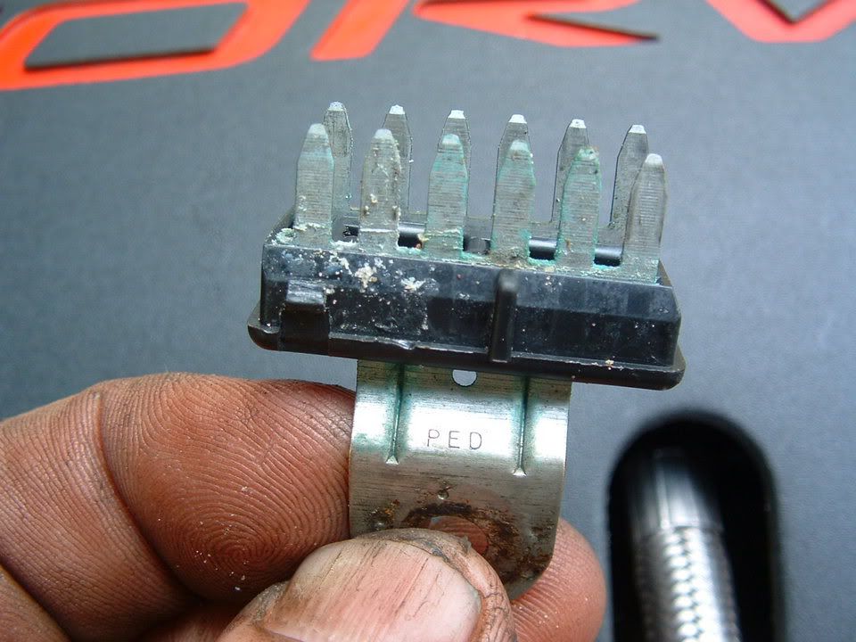
Here are some detailed pictures of the ground connector and the corrosion that was found inside it!
Picture of under hood Chassis Ground connector G-101
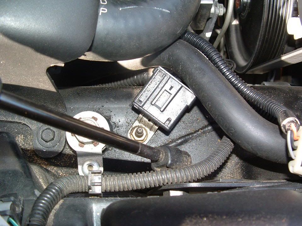
Corrosion inside connector! (You ain't seen nothing yet!)
[IMG][/IMG]
Next three photos are of the corrosion found on the connector terminals!
[IMG][/IMG] [IMG]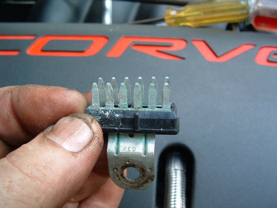 [/IMG] [IMG]
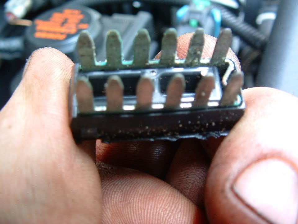 [/IMG]
Self tapping ground screw and star washer. This is what you will need if the ground stud breaks off during removal!
[IMG]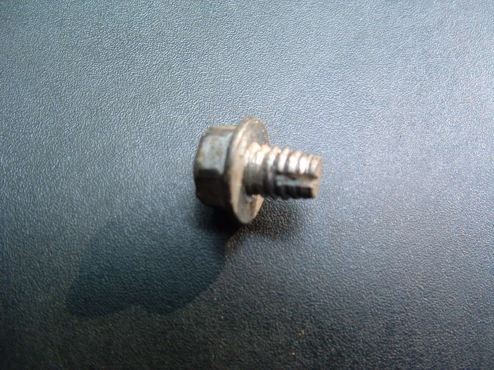 [/IMG] [IMG][IMG]
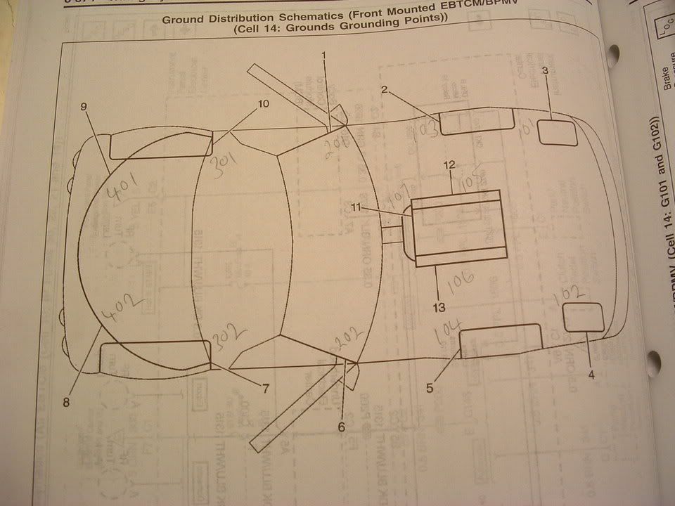
Here are where the chassis ground points are on a C5:
Attachment 48174127
Attachment 48174128
PLEASE let me know if you have any questions. NOTE! All of the pictures that I have of C5 Grounds have been posted on or in this post.
Bill Curlee
updated 02 March 06
My 98 coupe would get the infamous "REDUCED ENGINE POWER", "TRACTION CONTROL FAILURE" and a host of random failure codes. After many, many hours of troubleshooting, replacing the BCM and TAC module, I solved most of the driveability issues. Still getting the random DTC failure codes, I thought that I may be having ground issues. Back in June I cleaned ALL of the chassis grounds and the car virtually stopped throwing the "RANDOM" DTC failure codes. Just moving the wires in the chassis ground connector was enough to change the indications and make the issues stop happening.
I had a chance to speak with some GM C5 Trouble Desk Engineers when I went to Bowling Green KY in April and they pointed out that MANY of the C5 electrical issues can be directly linked to chassis ground problems. The engineer even went as far as to recommending that I chop off the factory under hood chassis ground connectors and combine all of the wires into a single ground lug. Not wanting to just LOP off the factory connector, I took a chance and disassembled one of the ground plug connectors and to my surprise it was indeed full of corroded connections.
I strongly recommend that any C5 owner that has had or who are having electrical issues, examine and clean the chassis ground connectors. This may save you from needlessly replacing expensive electronics modules. Each ground connector can be disassembled and cleaned in about 20 min.
Just cleaning the metal ground connection between the chassis and the plug is only a band aid solution. Now that I look back, when I cleaned my chassis grounds and initially solved my issues, I believe that when the connector is being removed to clean the connection between chassis and the connector, just the wires being moved inside the plug is what changed the indications and made everything work better.
Disassembly of the chassis ground plug and cleaning the contacts inside the connector is the correct method of solving the issue!
I took some pictures of the under hood chassis ground connector and the corrosion that was in it. I cleaned the two connections on the frame rails and the left one was significantly corroded! Taking it apart and cleaning it is a very straight forward procedure and I believe that if you follow this recommendation, you will be on the way to solving the many of the electrical issues.
Here are some detailed pictures of the ground connector and the corrosion that was found inside it!
Picture of under hood Chassis Ground connector G-101
Corrosion inside connector! (You ain't seen nothing yet!)
[IMG]
[/IMG] Next three photos are of the corrosion found on the connector terminals!
[IMG]
[/IMG] [IMG][/IMG] [IMG][/IMG] Self tapping ground screw and star washer. This is what you will need if the ground stud breaks off during removal!
[IMG]
[/IMG] [IMG][IMG]Here are where the chassis ground points are on a C5:
Attachment 48174127
Attachment 48174128
PLEASE let me know if you have any questions. NOTE! All of the pictures that I have of C5 Grounds have been posted on or in this post.
Bill Curlee
updated 02 March 06
Bill, I am having EBCM issues (C1214) and am trying to find ground point G103. The diagram shows it on drivers left and I can see what looks like G101 on the frame rail (based on your image) near the support arm for the hood, but I don't see anything aft of that except a ground strap. Any help in locating and identifying this would be greatly appreciated. Thanks, Dean