When you click on links to various merchants on this site and make a purchase, this can result in this site earning a commission. Affiliate programs and affiliations include, but are not limited to, the eBay Partner Network.
hello, I own a 1999 c5 corvette last week I got a low coolant on my dash and it appeared I had full coolant but I changed my coolant anyways because when I tried turning my car on it would first start cranking before the engine would finally start, and then it got worst as when I tried to change gears the engine would turn off and then i tried turning it on again and then it would run fine, but I got the "reduced engine power" I also got my check engine light I ran the code which was p1518, I decided I won't drive my car for a bit. but does anyone have any recommendation on what I should do or whats going on
hello, I own a 1999 c5 corvette last week I got a low coolant on my dash and it appeared I had full coolant but I changed my coolant anyways because when I tried turning my car on it would first start cranking before the engine would finally start, and then it got worst as when I tried to change gears the engine would turn off and then i tried turning it on again and then it would run fine, but I got the "reduced engine power" I also got my check engine light I ran the code which was p1518, I decided I won't drive my car for a bit. but does anyone have any recommendation on what I should do or whats going on
With a P1518 I would check for a weak battery first...next would be to get underneath the car and remove both connectors from the TAC module (sits below the PCM) and make sure there is no water intrusion...also check fuse 17 I believe but make sure you have power on both sides of the fuse using a test light...don't just look at the fuse...I would also check to make sure the throttle blade moves as you put your foot on the gas pedal...if this may be over your head because of the electrical testing involved I'd find an auto electric shop in your area...they would be better to diagnose this vs. a general repair shop or dealership...this may be a bad TAC module or even a bad PCM.
Dear Bill:
Thank you for your suggestions on cleaning ground connections on my C-5. Some time ago I had to replace my shocks and my mechanic wasn't able to locate the OEM GM units for Selective Real Time Damping that have the proper electrical connections. I have regular shocks now and the connections to the original GM shocks had been capped off. This was several years ago. Now about two months ago I am getting warning messages on the DIC, Shocks Inoperative, Service Ride Control. don't drive over 80 miles and so on seemingly out of the blue . Pushing the reset button on the control panel cancels it after starting engine but it is getting a bit annoying. I want to cancel that message permanently and hope your fix will work or if somebody has a way of cancelling this warning message permanently I would appreciate a response .
In regard to your fuel gauge issue. I had a problem were the indicator needle seemed to stick half way then suddenly drop to to E and would get the reserve fuel notice on the DIC.
I found a video, I think it was on YouTube that advised an easy fix was to simply add a container of Techron to the gas tank as directed. That cleared that problem right up for me.
It is an easy and cheap fix rather than replacing gas tank sensor. Maybe it would work for you or maybe not.
Todd
Best to post your concern in the C5 �Tech� section for best visibility !!�you can just copy and paste.
Best to post your concern in the C5 �Tech� section for best visibility !!�you can just copy and paste.
I thought my post didn't actually get posted here in that when I hit the submit button I got a message stating there was some issue going on with the server.
I thought my post didn't actually get posted here in that when I hit the submit button I got a message stating there was some issue going on with the server.
Todd
Just go to the Tech section and when you see �New Thread� post there !!
Getting these codes after intake change. Please I have 6 days into this car non stop
Originally Posted by Bill Curlee
Irish56
Yea,,you can skip quite a few!! It all depends on what kinds of issues your having. If you pin point the issue and include the DTC codes your getting. I can probably narrow it down to the EXACT ground wire!
The throttle position sensor circuit does not use any chassis grounds. It uses a dedicated circuit with a reference 5vdc wire, a signal wire and a circuit return wire. Have you removed the electrical connectors from the Throttle Body TPS sensor and made sure the connector, pins (both male and female) are clean and in good shape Same for the Accelerator Position Sensor. Is the throttle blade clean and free to move (key off)
Do you have a multimeter that you can use to measure the resistance of the TPS sensor on BOTH variable resistor circuits inside the sensor? One will be shut to fully open and the other will be fully open to shut
If you remove the air bridge, turn the key to ON (engine OFF) and have someone press and release the accelerator does the throttle blade open and shut smoothly?
The TPS has two resistor circuits inside the sensor. If you measure the voltage on one circuit, it will read 4.xx vdc and decrease to 0.xx vdc. The other circuit will read o.xx vdc and increase to 4.xx vdc. If you have a scanner, it may have a PID to see that digitally. See if you have the 5 vdc reference voltage on that circuit. Find the TAC fuse for the Throttle Actuation Control module and measure the voltage on the test points on top of the fuse to chassis ground (key ON) Make sure that you see full battery voltage on that fuse.
So I have triple checked all of that. Both the tps and the wiring for it. Including the 5v ref, grounds for both tps 1 and 2, and to make sure that the signal sent back to the tac module match�s on the wires. Everything was perfect. Throttle body is spotless, I cleaned it multiple times. I checked pids and there was no drop out of the sensors at all. And the throttle plate itself moves very smoothly. No out of wack resistance of the sensor itself. I will say the only thing I didn�t check that you just mentioned was verification of battery voltage on the tac module fuse. If I do not have 12v on the tac module fuse and let�s say it�s only 6v for example only, would I open up the fuse box and check for any corrosion/wire damage going to that fuse? I know that the fuse itself is not blown, that much I did check.
Not so fast... First, Pull the fuse and inspect the blades. Look for corrosion, blackening, and damage Then, break a fuse in half and use one spade to do a pin Push/Pull Test on the fuse slot female pins.
Next, One side of the fuse is the supply voltage side. The other is the load side. Use a volt meter and measure the supply voltage to ground. If it is still LOW, the supply voltage comes directly from the ignition switch. That will most likely be carboned up on the contacts for that circuit. Let us know what you find. You can also put an incandescent lamp on that circuit and when loaded down use a voltmeter to see if the voltage drops LOW when under load! That's the best way to test a circuit to see if can supply full voltage under a good load. .
If you clear the DTCs, what / when do they trip again. What actions causes the DTC to trip?
Alright I will try that out today! And as soon as I clear the codes that�s when I can use the gas pedal and actually actuate the throttle. Codes on I can�t do that. But when I clear the codes they will only stay off after I clear them, they come back as soon as I turn the key off then turn the key to KOEO
Just wanted to drop in and thank Bill for starting this thread as well as all the other contributors as I've referenced it dozens of times since acquiring a C5.
Also wanted to add that I think the ground splice packs are the most ridiculously lame bit of engineering I've seen out of GM. Yesterday I finally worked up the nerve and broke the badly rusted stud off and replaced the one next to the EBTCM with a soldered ring terminal. Thinking the best fix for these is do the same with all the other exterior ones. I have to wonder what kind of engineer thought it would be wise to put terminals that are critical for the operation of the vehicle in a connector with absolutely zero weatherproofing? Every part of the one I pulled apart had green on it.
think that through...engineers fault or the jerk off bean counter that squeezes every 1/100 penny from everything?.....and remains invisable to the consumer who in the end eats all costs.?
Everyone likes a less expensive product....but it gets to a ridiculous focus on saving too much $$$ on simple things that are already squeezed out....but thats just how it is.
I would like to thank the fine people WHO have shared the problems and fixes on their vette's....and other vehicles on these forums and you tube.
It benefits all who want to fix it themselves!
Many of you have asked me for help on solving electrical problems and I thought this would be VERY interesting!
My 98 coupe would get the infamous "REDUCED ENGINE POWER", "TRACTION CONTROL FAILURE" and a host of random failure codes. After many, many hours of troubleshooting, replacing the BCM and TAC module, I solved most of the driveability issues. Still getting the random DTC failure codes, I thought that I may be having ground issues. Back in June I cleaned ALL of the chassis grounds and the car virtually stopped throwing the "RANDOM" DTC failure codes. Just moving the wires in the chassis ground connector was enough to change the indications and make the issues stop happening.
I had a chance to speak with some GM C5 Trouble Desk Engineers when I went to Bowling Green KY in April and they pointed out that MANY of the C5 electrical issues can be directly linked to chassis ground problems. The engineer even went as far as to recommending that I chop off the factory under hood chassis ground connectors and combine all of the wires into a single ground lug. Not wanting to just LOP off the factory connector, I took a chance and disassembled one of the ground plug connectors and to my surprise it was indeed full of corroded connections.
I strongly recommend that any C5 owner that has had or who are having electrical issues, examine and clean the chassis ground connectors. This may save you from needlessly replacing expensive electronics modules. Each ground connector can be disassembled and cleaned in about 20 min.
Just cleaning the metal ground connection between the chassis and the plug is only a band aid solution. Now that I look back, when I cleaned my chassis grounds and initially solved my issues, I believe that when the connector is being removed to clean the connection between chassis and the connector, just the wires being moved inside the plug is what changed the indications and made everything work better.
Disassembly of the chassis ground plug and cleaning the contacts inside the connector is the correct method of solving the issue!
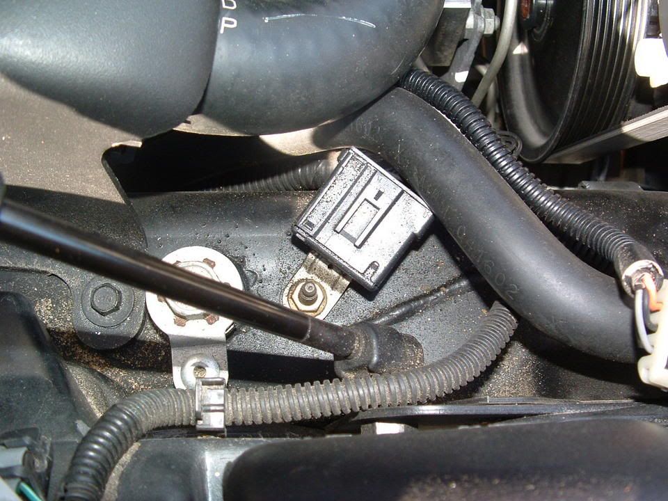
I took some pictures of the under hood chassis ground connector and the corrosion that was in it. I cleaned the two connections on the frame rails and the left one was significantly corroded! Taking it apart and cleaning it is a very straight forward procedure and I believe that if you follow this recommendation, you will be on the way to solving the many of the electrical issues.
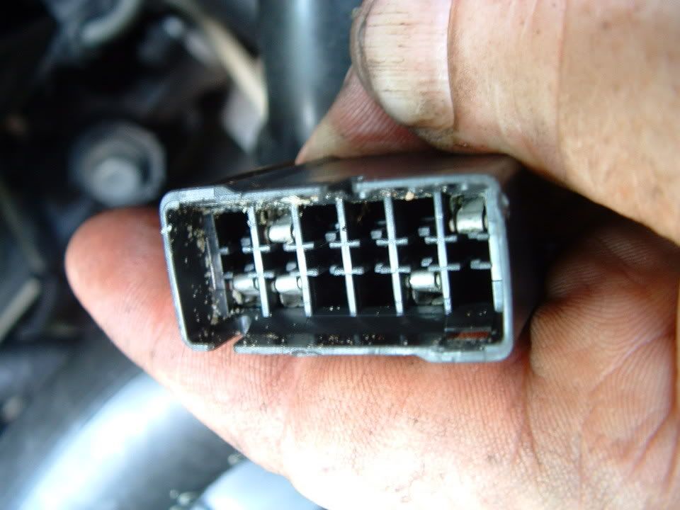
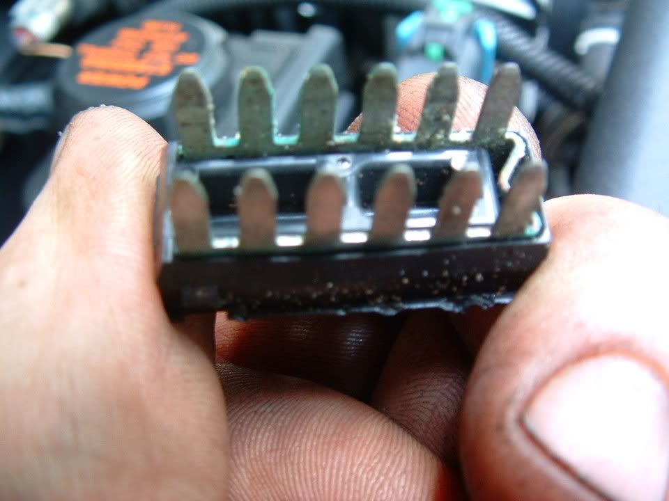
Here are some detailed pictures of the ground connector and the corrosion that was found inside it!
Picture of under hood Chassis Ground connector G-101
Corrosion inside connector! (You ain't seen nothing yet!)
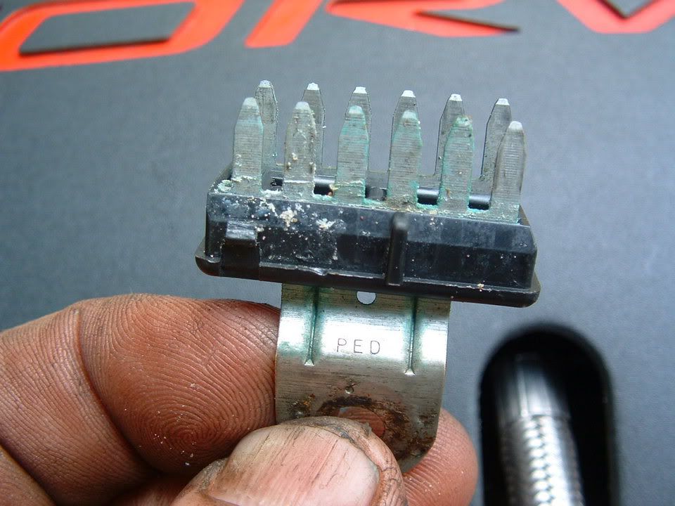
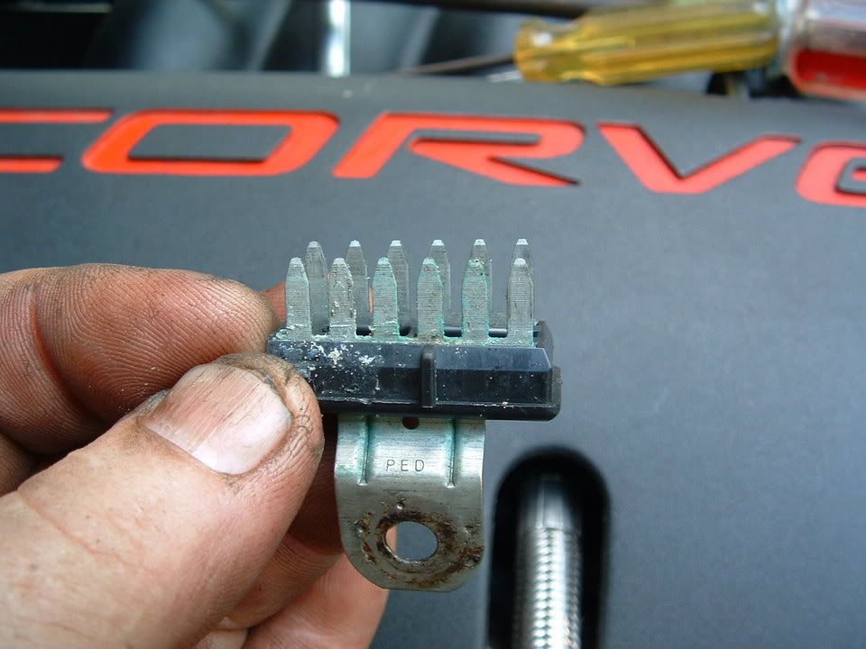
Next three photos are of the corrosion found on the connector terminals!
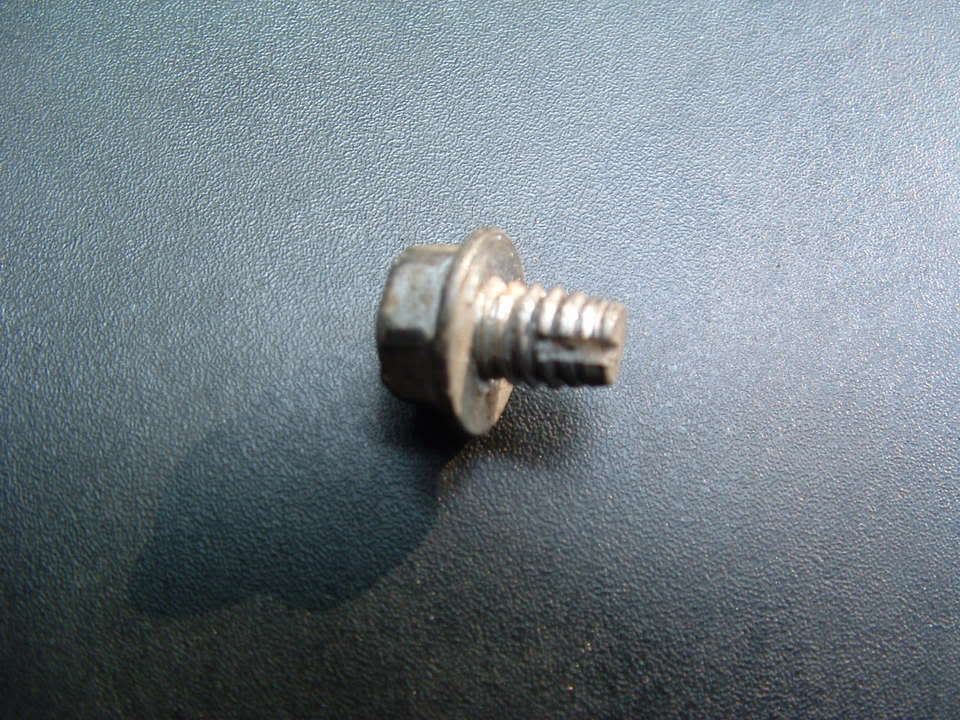
Self tapping ground screw and star washer. This is what you will need if the ground stud breaks off during removal!
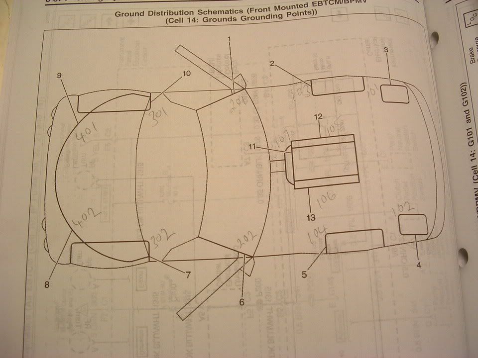
Here are where the chassis ground points are on a C5:
Any pictures of the unified mass of negative wires at each of the front locations? What gauge loop crimp-on connector did you use after putting them together and did you add solder to them before crimping it?
I have a 02 Z06 with only 12K on it .. My 1st GM product .. Sure picked a winner .. I'm going to take your lead and go after the grounds first just to get it done clear the codes and establish a base line .. My active handling /ABS lite is on and won't reset and today I put it on the lift to ck the trans and Diff fluids and back off and get a CK engine lite .. I don't have any GM tech info so I'm flying VFR in IFR conditions .. After doing some reading in the forums it seems like some of the code intersect and maybe thats part of my problems .. I got 9 codes back after I cleared them .. And I have not cleaned the grounds yet .. Also to you use a diletric grease on ground connectors like on the left front ?.. Any help and guidance will be greatly appreciated
B0432
C1235 - C1277 - C1283
P0170 - P0174 - P1571 - P1689
U1040
Pull up a wiring diagram to see if those codes (sensors) share common ground. Bet they do.
Grease goes on top of final project not between contact surfaces
Hi Bill,
What did you use to clean the connector up behind the headlight? just some steel wool?
Also, I needed to remove the rear bumper and the last bolt that I could not get undone was the upper right passenger side that had a double nut with a sandwiched washer. What is this ground for? I see that there is braided strap that runs up to the base of the antenna and then a second braided strap runs from the base down to the rear crash bar. The bolt came out fairly easy with a 10mm socket but I had to snip the wires because I didn't know there was a second washer behind the first one which I couldn't get a wrench on (side note that bolt is a 12mm or 13mm). There was a black wire that came from the rear fender back to this bolt and then another black wire that followed the upper lip of the trunk well as well and then just dead ended half way across (I'm not sure what that is for). Below are a few pictures that I have taken in all of this process.
On my 2001 Convertible I have been into that area. And what you show looks like the ground for the power antenna, and the antenna itself. I don't know beans about what kind of ground antennae require. But I did swap out my powered antenna for a stubby.
Dear Forum administrator:
I did not post the original inquiry in regard to the grounding and other electrical issues on a convertible C-5. The replies are being directed to me and perhaps not the person who needs the info.
TPacifica