


IMPORTANT ELECTRICAL INFORMATION (Long!)
Instructor


Joined: Jun 2008
Posts: 119
Likes: 2
C5 with 14k miles - I charged the bat for the a day, left it out. I put it back in last night. Used the spare key and it started with out a problem. darn new technology. My c2 sat all winter long. Cranked over about 5 times and fired right up.

Racer

Joined: May 2001
Posts: 253
Likes: 3
From: The Woodlands Texas

Thread Starter
Tech Contributor


Joined: Dec 1999
Posts: 32,910
Likes: 2,402
From: Anthony TX
CI 6,7,8,9,11 Vet
St. Jude Donor '08
4th Gear
Joined: Jul 2008
Posts: 4
Likes: 0
From: Pawleys Island SC
2001 ZO6 - only code is TCS 1214....both ABS and TC lights on
Thanks BC - I have ruled out all the simple fixes, and I am hopeful with ABS fixer.
Thanks BC - I have ruled out all the simple fixes, and I am hopeful with ABS fixer.
Last edited by gregrule; Jul 18, 2008 at 12:46 AM. Reason: Obsolete

1st Gear
Joined: May 2008
Posts: 1
Likes: 0
Dear Sticky,
THANKYOU!
I was showing off my 2002 ZO6 to a buddy, and I couldn'y get it into third, and then the clutch wanted to release real deep for a while. I heard you couldn't power shift with the hydraulic clutch.
Two more starts and it said "reduced engine power", "service traction control" . Engine light on. OBD II test revealed P1220, throttle position sensor.
I found the ground behind the drivers headlight to be only a little more than finger tight. I sanded the bottom of the post, put dielectric grease on it, and left the battery disconnected for a while (over an hour)
After start, all back to normal, running like a champ.
Many thanks, and no money wasted.
Tom Sky Dog
Corvette Stories
The Best of Corvette for Corvette Enthusiasts

Top 10 Most Expensive Corvettes Ever Sold on Bring A Trailer
Brett Foote
10 Things Every Corvette Owner Needs (2026 Edition)
Michael S. Palmer
8 Most "Only Corvette Owners Understand" Quirks and Problems
Pouria Savadkouei
10 Reasons the C6 Z06 is Still A Performance Benchmark After 20 Years
Joe Kucinski
How Much Horsepower Every Corvette Engine "LOST" in 1972
Joe Kucinski
Top 10 DOs and DON'Ts for Protecting Your Convertible Top!
Michael S. Palmer
Top 10 Most Explosive Corvettes Ever Made: Power-to-Weight Ratio Ranked!
Joe Kucinski
150 hp to 1,250 hp: Every Corvette Generation Compared by the Specs That Matter
Joe Kucinski
8 Coolest Corvette Pace Cars (and Replicas) of All Time
Verdad GallardoRace Director

Joined: Aug 2001
Posts: 11,028
Likes: 5
From: Chicago (Naperville) IL
I'm back... I read through all the posts.
Here are the codes I wrote down early this week and then cleared them...
10-PCM
P1571H ASR Desired Torque
28-TCS
C1277H Requested Torque Signal CKT Malfunction
60-IPC
B0521H Tachometer Signal Circuit Malfunction
80-Radio
U1016H Loss of communication with PCM
LDCM
B2285H Battery #2 Fault
B2282H Battery #1 Fault
B2284H Battery #2 Fault
U1064H Loss of Communication with BCM
U1160H
---------
I was only getting "service traction system" (only - ABS was fine) before, when I pressed down on the brake to shift out of park or reverse. A few days ago, I was driving on a bumpy road and got service traction system and ABS inactive , so the warnings came on for the first time while I was driving.
Just checked the codes again and here are the ones that are there now...
10-PCM
P1571 H C ASR Desired Torque
28-TCS
C1277H Requested Torque Signal CKT Malfunction
C1225H RF Excessive Wheel Speed variation <----------NEW ONE
80 Radio
U1016H Loss of communication with PCM
So, based on reading this thread I should check the sensor that is on the RF wheel hub and make sure the connection is good - where on the inner hub is the wire with the connector? Top, bottom, towards the front of the Vette, etc? The pics show the hub removed from the Vette. I am not going to disconnect the battery, hopefully, that is OK. How about the other three codes, 2 noting torque - any ideas?
Also, I found this thread with a guy with a 97 A4 like me and is getting the same codes - I pm'd him too - hopefully he'll respond.
http://forums.corvetteforum.com/show...ighlight=P1571
What should I be looking for in regards to the PCM and BCM connections? These are under the battery right? I have an optima red top, so I don't think my battery is leaking.
Thanks
Here are the codes I wrote down early this week and then cleared them...
10-PCM
P1571H ASR Desired Torque
28-TCS
C1277H Requested Torque Signal CKT Malfunction
60-IPC
B0521H Tachometer Signal Circuit Malfunction
80-Radio
U1016H Loss of communication with PCM
LDCM
B2285H Battery #2 Fault
B2282H Battery #1 Fault
B2284H Battery #2 Fault
U1064H Loss of Communication with BCM
U1160H
---------
I was only getting "service traction system" (only - ABS was fine) before, when I pressed down on the brake to shift out of park or reverse. A few days ago, I was driving on a bumpy road and got service traction system and ABS inactive
, so the warnings came on for the first time while I was driving.Just checked the codes again and here are the ones that are there now...
10-PCM
P1571 H C ASR Desired Torque
28-TCS
C1277H Requested Torque Signal CKT Malfunction
C1225H RF Excessive Wheel Speed variation <----------NEW ONE
80 Radio
U1016H Loss of communication with PCM
So, based on reading this thread I should check the sensor that is on the RF wheel hub and make sure the connection is good - where on the inner hub is the wire with the connector? Top, bottom, towards the front of the Vette, etc? The pics show the hub removed from the Vette. I am not going to disconnect the battery, hopefully, that is OK. How about the other three codes, 2 noting torque - any ideas?
Also, I found this thread with a guy with a 97 A4 like me and is getting the same codes - I pm'd him too - hopefully he'll respond.
http://forums.corvetteforum.com/show...ighlight=P1571
What should I be looking for in regards to the PCM and BCM connections? These are under the battery right? I have an optima red top, so I don't think my battery is leaking.
Thanks
 - $1900
any help from you guys would be appreciated, still looking for help


Thread Starter
Tech Contributor
Joined: Dec 1999
Posts: 32,910
Likes: 2,402
From: Anthony TX
CI 6,7,8,9,11 Vet
St. Jude Donor '08
Dear Sticky,
THANKYOU!
I was showing off my 2002 ZO6 to a buddy, and I couldn'y get it into third, and then the clutch wanted to release real deep for a while. I heard you couldn't power shift with the hydraulic clutch.
Two more starts and it said "reduced engine power", "service traction control" . Engine light on. OBD II test revealed P1220, throttle position sensor.
I found the ground behind the drivers headlight to be only a little more than finger tight. I sanded the bottom of the post, put dielectric grease on it, and left the battery disconnected for a while (over an hour)
After start, all back to normal, running like a champ.
Many thanks, and no money wasted.
Tom Sky Dog
THANKYOU!
I was showing off my 2002 ZO6 to a buddy, and I couldn'y get it into third, and then the clutch wanted to release real deep for a while. I heard you couldn't power shift with the hydraulic clutch.
Two more starts and it said "reduced engine power", "service traction control" . Engine light on. OBD II test revealed P1220, throttle position sensor.
I found the ground behind the drivers headlight to be only a little more than finger tight. I sanded the bottom of the post, put dielectric grease on it, and left the battery disconnected for a while (over an hour)
After start, all back to normal, running like a champ.
Many thanks, and no money wasted.
Tom Sky Dog
 Please describe what you mean by power shift?
 That sounds like bum dope BUT,,it all depends on what your calling POWER SHIFTING. If what your talking about shifting without taking your foot off the accelator, then that is a BAD thing in a C5 trans unless you have a stage IV from Rodney!
 If you have a stage IV there are people who accomplish it without issue.
 If everything in your drive train is mechanically correct and properly up-graded, it will do it with missing a beat!
If your talking about SPEED SHIFTING ,,,shifting very quickly,,,That is easly doable I do it all the time.
BC
BC
Last edited by Bill Curlee; Jul 23, 2008 at 05:25 PM.

Heel & Toe
Joined: Jul 2008
Posts: 19
Likes: 0
From: Smithtown New York
I attempted to remove the G-101 ground connector bolt from the post but it was so tight I was unable to do so. Is it possible to separate and clean the connector from the connector terminals with the bolt in place? Thanks for the help.
Last edited by facc5; Jul 24, 2008 at 01:35 PM.

Le Mans Master


Joined: May 2006
Posts: 6,774
Likes: 363
From: Midland TX
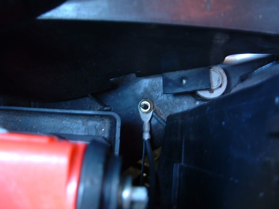
Perhaps I missed it, but I did not see any photos of the G-106 Ground point? I took this photo tonight while checking mine.
Bill - If you see anything wrong on this photo, please let me know and I will correct it...

Bill - If you see anything wrong on this photo, please let me know and I will correct it...
Thread Starter
Tech Contributor
Joined: Dec 1999
Posts: 32,910
Likes: 2,402
From: Anthony TX
CI 6,7,8,9,11 Vet
St. Jude Donor '08
Instructor
Joined: May 2008
Posts: 149
Likes: 0
From: Twain Harte CA
Choreo,
Absent the GM chassis electrical manual and listed torque values, here's what I've done over the years with any electrical connections on any vehicle:
Use a nut driver (or if a screw is used on smaller connections) or screwdriver - - manual only. Don't use a power screw driver or nut driver/socket or there's a danger you'll strip the threads. Tighten as snugly as possible.
For large chassis ground connections directly bolted to the frame, engine block, or connection block, use the proper sized socket and NO LARGER THAN A STANDARD 3/8" ratchet (handle lenght 6" or less). Snug down to where the head of the bolt or screw makes contact and "shoulders' fully against the frame, etc. Tighten one-half to one full turn more, or if the bolt is large enough, until you cannot tighten any further.
Last edited by bassman12350; Jul 29, 2008 at 02:27 PM. Reason: Grammar
Thread Starter
Tech Contributor
Joined: Dec 1999
Posts: 32,910
Likes: 2,402
From: Anthony TX
CI 6,7,8,9,11 Vet
St. Jude Donor '08
A number of people have written and asked me to provide them pictures and locations of the C5 Chassis Ground locations. It looks like the Photobucket links are not working so,,,,I'm going to repost them here:
Here are the Chassis Ground points:


The Chassis Ground Connectors are either a non weather tight plug style:

This style can be disassembled. There is a small latch on each side. You should insert a small flat head screwdriver under each latch and at the same time, use a pair of pliers to grip the metal tang and pull.


If your as unfortunately as me and the stud breaks, not to worry. There is a work around.

Just grind the area where the stud broke from FLAT with a grinder and drill a small hole for a self tapping screw:


Fixed!!

The other type of ground is a stud eyelet type:
This is G-104 / 108 next to the battery.
The grounds on the engine are eyelet type grounds. Most are secured to the engine with a 15mm bolt.
BC
Here are the Chassis Ground points:
The Chassis Ground Connectors are either a non weather tight plug style:
This style can be disassembled. There is a small latch on each side. You should insert a small flat head screwdriver under each latch and at the same time, use a pair of pliers to grip the metal tang and pull.
If your as unfortunately as me and the stud breaks, not to worry. There is a work around.
Just grind the area where the stud broke from FLAT with a grinder and drill a small hole for a self tapping screw:
Fixed!!
The other type of ground is a stud eyelet type:
This is G-104 / 108 next to the battery.
The grounds on the engine are eyelet type grounds. Most are secured to the engine with a 15mm bolt.
BC
Last edited by Bill Curlee; Jul 29, 2008 at 05:36 PM.
Thread Starter
Tech Contributor
Joined: Dec 1999
Posts: 32,910
Likes: 2,402
From: Anthony TX
CI 6,7,8,9,11 Vet
St. Jude Donor '08
While Im updating,,I will add the C5 Ignition Switch Repair information to this post:
C5 Ignition Switch Repair
by Bill Curlee
There have been quite a few forum members with IGNITION SWITCH failure. There are a number of different symptoms to indicate that the switch is bad.
I helped FASTVETZO6 ( Mark) troubleshoot his problem down to the ignition switch. After replacement of the ignition switch, his problems were resolved. He mailed his old switch to me and I have dissected it, figured out why they fail and detailed the switch repair!
Thanks for the switch Mark! You made my weekend!
Here is the switch removed from the car The ignition lock cylinder has been removed. This is how you will receive the new switch from GM:


Looks complicated but its really very simple. The first step is to use an ohm meter to see if the switch is really bad before disassembly. I have included a hand drawn schematic of the switch PLEASE excuse the roughness of the drawing.

Use an ohm meter and ohm out each contact. You will need to cycle the switch through OFF, ACC, ON and Crank. Each contact point should be 0-5 ohms. Marks switch was reading 2500 + ohms on contacts 5 & D and 2000 ohms on contacts 3 & E.
( NOTE! The contact letters and numbers do NOT correspond to the C5 schematics. I added my own letters and numbers to help explain the drawing!
The switch contacts in the center area of the switch are the contacts that tell the BCM if the ignition KEY is inserted in the ignition cylinder or not.
Once you determine that the contacts are good or bad, remove the top GREEN cover to expose the switch contacts. The cover is easily removed by prying up the tabs "evenly" with a screwdriver.

Once the cover is off, this is what you will see:

Lift out the movable contact strips noting how the movable contacts and springs on top of the contact arms are assembled. The springs can and will fall off the arms!
Once the contacts are out, this is what you will see:

In Marks switch you can see TWO distinct burnt contacts. Those were the bad contacts.

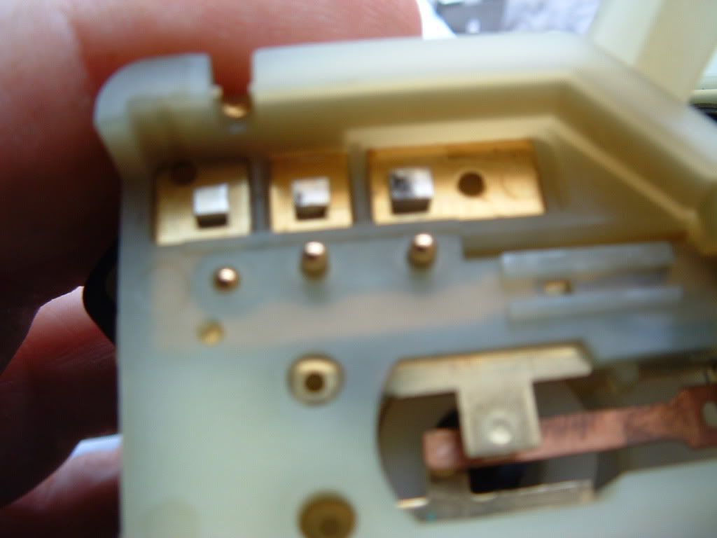
The small brass pins just inside the fixed contacts are the pins that move UP & DOWN to operate the contacts.
The section of the switch below the section shown in the pictures above only contains the cam to move the brass pins UP & DOWN to operate the movable switch arms and contain NO electrical contacts. There is no need to disassemble this portion of the switch. When you rotate the switch the brass contacts will move UP or DOWN with each position of the switch.
There is a legend next to the hand drawn schematic that explains how the pins operate when the switch is moved through the various positions of the ignition switch.
I believe that the movable contact arms loose spring tension and cause poor contact and that results in contact arcing. Here is what the arms looked like when removed. The arm is slightly bent back wards:

Here is the burnt contacts on the arms:


I used 2000 grit wet & dry sand paper to clean the fixed and movable contacts. Polish the contacts clean to remove carbon and pitting.

Once there polished clean, wipe them down with alcohol.
(Part 2 continued in next post)
C5 Ignition Switch Repair
by Bill Curlee
There have been quite a few forum members with IGNITION SWITCH failure. There are a number of different symptoms to indicate that the switch is bad.
I helped FASTVETZO6 ( Mark) troubleshoot his problem down to the ignition switch. After replacement of the ignition switch, his problems were resolved. He mailed his old switch to me and I have dissected it, figured out why they fail and detailed the switch repair!
Thanks for the switch Mark! You made my weekend!
Here is the switch removed from the car The ignition lock cylinder has been removed. This is how you will receive the new switch from GM:
Looks complicated but its really very simple. The first step is to use an ohm meter to see if the switch is really bad before disassembly. I have included a hand drawn schematic of the switch PLEASE excuse the roughness of the drawing.
Use an ohm meter and ohm out each contact. You will need to cycle the switch through OFF, ACC, ON and Crank. Each contact point should be 0-5 ohms. Marks switch was reading 2500 + ohms on contacts 5 & D and 2000 ohms on contacts 3 & E.
( NOTE! The contact letters and numbers do NOT correspond to the C5 schematics. I added my own letters and numbers to help explain the drawing!
The switch contacts in the center area of the switch are the contacts that tell the BCM if the ignition KEY is inserted in the ignition cylinder or not.
Once you determine that the contacts are good or bad, remove the top GREEN cover to expose the switch contacts. The cover is easily removed by prying up the tabs "evenly" with a screwdriver.
Once the cover is off, this is what you will see:
Lift out the movable contact strips noting how the movable contacts and springs on top of the contact arms are assembled. The springs can and will fall off the arms!
Once the contacts are out, this is what you will see:
In Marks switch you can see TWO distinct burnt contacts. Those were the bad contacts.
The small brass pins just inside the fixed contacts are the pins that move UP & DOWN to operate the contacts.
The section of the switch below the section shown in the pictures above only contains the cam to move the brass pins UP & DOWN to operate the movable switch arms and contain NO electrical contacts. There is no need to disassemble this portion of the switch. When you rotate the switch the brass contacts will move UP or DOWN with each position of the switch.
There is a legend next to the hand drawn schematic that explains how the pins operate when the switch is moved through the various positions of the ignition switch.
I believe that the movable contact arms loose spring tension and cause poor contact and that results in contact arcing. Here is what the arms looked like when removed. The arm is slightly bent back wards:
Here is the burnt contacts on the arms:
I used 2000 grit wet & dry sand paper to clean the fixed and movable contacts. Polish the contacts clean to remove carbon and pitting.
Once there polished clean, wipe them down with alcohol.
(Part 2 continued in next post)
Thread Starter
Tech Contributor
Joined: Dec 1999
Posts: 32,910
Likes: 2,402
From: Anthony TX
CI 6,7,8,9,11 Vet
St. Jude Donor '08
Here are all the contacts cleaned up:

I used a mechanical pencil with sand paper glued to the eraser to clean the fixed contacts. The eraser was trimmed down to fit the recess in the switch housing:


Once the contacts are cleaned up, bend the contact arms so that they apply more tension on the fixed contacts. It doesn't need too much bending:

Once you apply more tension to the contacts, you will need to be careful when reinserting the arms back into the switch. The movable contact pads will tend to hang up on the fixed contacts. Assist them over the fixed contacts. I used a hooked paper clip to raise the arm over the fixed contact.
I used two flat blade screwdrivers to apply force to contacts A & B inside the switch contact well to keep the contact arms forced down on the fixed contacts to prevent them from popping out of place while installing the green cap. Once the contacts are in place,

snap the green cap back on the switch. Check the CLEANED contacts with an ohm meter. They should read very close to ZERO OHMS.
Please feel free to ask me any questions that you have. I feel I'm a IGNITION SWITCH expert now!
Marks old NASTY broken switch is as good as new!!!!!!!!!!

BC
I used a mechanical pencil with sand paper glued to the eraser to clean the fixed contacts. The eraser was trimmed down to fit the recess in the switch housing:
Once the contacts are cleaned up, bend the contact arms so that they apply more tension on the fixed contacts. It doesn't need too much bending:
Once you apply more tension to the contacts, you will need to be careful when reinserting the arms back into the switch. The movable contact pads will tend to hang up on the fixed contacts. Assist them over the fixed contacts. I used a hooked paper clip to raise the arm over the fixed contact.
I used two flat blade screwdrivers to apply force to contacts A & B inside the switch contact well to keep the contact arms forced down on the fixed contacts to prevent them from popping out of place while installing the green cap. Once the contacts are in place,
snap the green cap back on the switch. Check the CLEANED contacts with an ohm meter. They should read very close to ZERO OHMS.
Please feel free to ask me any questions that you have. I feel I'm a IGNITION SWITCH expert now!
Marks old NASTY broken switch is as good as new!!!!!!!!!!
BC
Heel & Toe
Joined: Jul 2008
Posts: 19
Likes: 0
From: Smithtown New York
My 2001 coupe has both a non weather tight plug style connector and a stud eyelet connector on the g-101 ground. Is this normal? Could this cause illumination of the TC/ABS lights?
Frank Cervo
Frank Cervo