


IMPORTANT ELECTRICAL INFORMATION (Long!)

Thread Starter
Tech Contributor


Joined: Dec 1999
Posts: 32,910
Likes: 2,402
From: Anthony TX
CI 6,7,8,9,11 Vet
St. Jude Donor '08
Good Morning, Bill... 3:00am here at the moment. I've just decided to BURN this set of Factory Manuals. ugh! "Heads Up Display", what they cover in the manual, this could be an Owner's Manual.
My Problem... Last night driving home the 'Guage' section of the HUD disappeared.
The Speedo and Tach are still displaying, fully functional and adjustable.
But the right side of the HUD, the guage, is 'out'.
Before I go pulling this item out of the dash, (no small feat in itself), is there a bulb that can be replaced? or is this a 'whole unit' item, where I need a new HUD complete?
Thanks in advance, and the blessings of Zora Duntov upon you.
Your problem is in the projector inside the HUD. If you can see HALF the display, its an internal issue inside the projector.
DELPHI or who ever makes the electronics have poor solder quality. It could very well be a poor solder joint on the board OR a poor connection where it connects to the wiring harness.
If it were me, I would rip it apart and see if you have any circuit board or internal wiring connection issues.
If you apply some mechanical agitation to the top of the HUD module, does the display change ???
Bil
Burning Brakes


Joined: Oct 2013
Posts: 1,030
Likes: 72
From: Seminole, FL
Thanks for the info, Bill.
But it was PEBKAC !!! Problem Exists Between Keyboard and Chair.
Read in the Service Manual about the Diagnostic Startup Proceedure, how the display "Lights Everything" quickly at Key-On. Never noticed this before.
I do now! The entire display is functional. Not the Driver. Duh.
Back to the WWW for "HUD Display Functions"
Pressed and HELD the PAGE button Display went to MPH only.
Then page button again 'till desired sections present.
Apparently, "Stupid Fingers" was the problem?
Everything as it should be.
Le Mans Master


Joined: Jul 2011
Posts: 7,426
Likes: 970
From: Morristown New Jersey
Oldtimer
Hey Bill, 8VETTE7 referred me to the beginning of this thread where you show diagrams of C5 ground points. They look like pages from a manual. Do you remember which one?
Thanks!
Thanks!
Thread Starter
Tech Contributor
Joined: Dec 1999
Posts: 32,910
Likes: 2,402
From: Anthony TX
CI 6,7,8,9,11 Vet
St. Jude Donor '08
If its a picture of the page, its a 98 C5 service manual page. I have the complete 98 service manual as well as the 2001 and 2004 service manual.
I also have ESI Service manuals on DVD and I can pull up and post any year C5 schematic as well as most other 97-2005 GM platform.
Normally I post an early C5 or a late model C5 document That can be a early 98-99 or a late 2001, 2002 or 2003..
The 2004 is a platform that I usually post stuff for 2004 specific because a lot of things changed. Same for 97,, it can be a one off that year specific thing.
Early BC stuff was most likely a 98 C5.
Bill

Melting Slicks

Joined: Sep 2011
Posts: 3,498
Likes: 680
From: The beautiful Alabama Gulf Coast!!
Getting the connectors separated is a real pain!! I tried for about an hour to get the one under the hood on the driver side frame rail apart without any success whatsoever. I'll try again tomorrow maybe... 
Le Mans Master
Joined: Jul 2011
Posts: 7,426
Likes: 970
From: Morristown New Jersey
Oldtimer
 the big one behind the cluster was initially tough until I understood it.

mike v

Joined: Feb 2013
Posts: 465
Likes: 92
From: Riner Va
Sent to Mr Curlee, but would like any info I can find at thsi time...
Dear Mr. Curlee,
I'm Mike Venth, A Corvette forum member.
Can you HELP please?
2001 coupe. 58K mls.
Starting back in July (2013) started having a problem with my 01 vet starting, shutting off, runs then shuts off, a few miles shuts off, some times stays running for days, sometimes wont start. I have read all the forums, and followed everyone�s (and all of your) suggestions to the T. Still not fixed�.
This is what I have done so far: Cleaned all but 4 grounds. On ground s# 101,102,301,302 after cleaning still no progress, so I cut the wires on (#101,102) and soldered them to single connectors. Also Run a new ground on top of 101,102, 301, 302 and spliced them back (all together-single loop) back to the Battery-Neg ground on the frame. Also on some occasions I get a low oil read-out. Take off NEG Ground over night and it goes out, mostly it just won�t start or stay running.
This is what I have replaced so far.
NEW: all o2�s ,, spark plugs & wires,,, mass air flow sensor,,, Battery,,, Low oil sensor,,,Ignition switch,,, ECM/PCM with Flashing-re-programmed and Up dated,,, Manifold absolute pressure sensor,,, Engine oil pressure sensor,,, Camshaft sensor, Crank shaft sensor,,, Fuel filter/regulator,,, And new Fuel Pump�� All NEW parts.
Can you help me with 2 things,
1.Where specifiable, are ground wires # 201,202, 301, 302 located????
2.And what am I overlooking?????
Any suggestions, information, and Help would be thankful.
Mike Venth
Corvette Stories
The Best of Corvette for Corvette Enthusiasts

Top 10 Most Expensive Corvettes Ever Sold on Bring A Trailer
Brett Foote
10 Things Every Corvette Owner Needs (2026 Edition)
Michael S. Palmer
8 Most "Only Corvette Owners Understand" Quirks and Problems
Pouria Savadkouei
10 Reasons the C6 Z06 is Still A Performance Benchmark After 20 Years
Joe Kucinski
How Much Horsepower Every Corvette Engine "LOST" in 1972
Joe Kucinski
Top 10 DOs and DON'Ts for Protecting Your Convertible Top!
Michael S. Palmer
Top 10 Most Explosive Corvettes Ever Made: Power-to-Weight Ratio Ranked!
Joe Kucinski
150 hp to 1,250 hp: Every Corvette Generation Compared by the Specs That Matter
Joe Kucinski
8 Coolest Corvette Pace Cars (and Replicas) of All Time
Verdad Gallardo
Thread Starter
Tech Contributor
Joined: Dec 1999
Posts: 32,910
Likes: 2,402
From: Anthony TX
CI 6,7,8,9,11 Vet
St. Jude Donor '08
Mike
I answered your PM via e-mail reply. My very first thoughts would be your ignition switch BUT,,, when the engine quits,,, If you read the DTC,, without changing ANYTHING,, what do you get??
If you have none, the PCM thinks that it was shut down normaly.
Check the DTCs If there are a lot of old ones, clear them all and report what comes back during the issue.
Bill
Thread Starter
Tech Contributor
Joined: Dec 1999
Posts: 32,910
Likes: 2,402
From: Anthony TX
CI 6,7,8,9,11 Vet
St. Jude Donor '08
Bill

Burning Brakes
Joined: Feb 2012
Posts: 901
Likes: 2
From: Palm City Fl
I have written on here a few times about my throttle jumping to 3800 RPM and sticking there. I thought the problem was solved when I replaced the battery, as the problem seemed to just go away for quite a while after that. Well its back. I usually get the "reduced engine power" first, but not always. I wrote the codes down it throws but don't have them with me right now. I always get "fuel pump secondary circuit low" with the "reduced engine power". I get two other codes when the throttle sticks, I think they are do to the problem not the cause. One is throttle position demand vs actual and I forget what the other is off hand. I drive with a code reader connected so when this happens I can clear the codes and all goes back to normal. Not sure why it took me so long to wonder this, but what would clearing the codes do to release the throttle? What would be getting locked in that would only clear with clearing the codes, that wouldn't clear on its own if the problem that caused it is no longer there? I am really getting frustrated with this. I have noticed my voltage changes quite a bit, and I can see my lights dim at night when the voltage drops. My wife's 99 coupe seems like it doesn't go below 13.4 Volts where as my 02 Z will sometimes drop to low 12s. I am not sure if it drops low and that is giving me this throttle problem, but I don't really think so. PLEASE HELP.....
Thread Starter
Tech Contributor
Joined: Dec 1999
Posts: 32,910
Likes: 2,402
From: Anthony TX
CI 6,7,8,9,11 Vet
St. Jude Donor '08
LT
There are SOOOOOOOOOOOOOOOOOO many things to examine and explain but we will start with a few simple things.
1. The voltage reading. The two gages in the IPC Digital and analogue are NOT actual battery voltage. The indicate a voltage AFTER the ignition switch.
To get an actual voltage reading you will need a DC Volt meter. You can read the voltage at the battery terminals OR the Cigar lighter (with a plug and pig tail)
If your ignition switch has dirty contacts, it can limit voltage output on those dirty contacts.
Service/clean or replace the switch if it reading reduced output.
You say that you are reading DTCs with a CODE READER??? Why are you not using the built in reader? It can and will do the reading and clearing of DTCs.
The next time that the throttle sticks or jumps to the high RPM,, Read the DTCs using the DIC and write them down..
Examine the engine wiring harness that runs down the drivers valve cover and down to the back of the engine. Look closely at where it bends around the metal bracket at the back of the fuel rail and look for chaffed wires.
BC
Burning Brakes
Joined: Feb 2012
Posts: 901
Likes: 2
From: Palm City Fl
Bill, thanks for your fast reply.
I did take the codes off the built in reader, I just use the hand held so I can clear the codes while I am driving more easily. The codes are as follows.
PCM: P0106
P1221 H C TP Sensor 1 - 2 Performance
P1516 H C Command vs Actual TP Performance
P1415 H C Air System Bank 1
The last code, 1415, I have been getting ever since I had the blower installed (tvs 2300). The car also has long tube headers and non catted X pipe.
I do not get all these codes every time it happens either. Today when I read the codes the P0106 code was not in. I think that is the one for Fuel Pump Secondary Circuit Low. I am using Service Manuals for my 99 coupe. I know I should get a set for my 02Z too. lol
I should mention that I also have TCS Code C1214 and C1278. The 1278 will clear but the 1214 will not. I realize that I most likely have a bad relay in the EBCM. I doubt there is any connection between the two problems, but until the 1214 code locked in they all used to come in within seconds of each other.
I have changed the TP sensor with a spare I had, but it did not help. I did find that if I unplug the TPS or the throttle positioner the car jumps right to about 3800 RPM, just as it does when I am driving. I have not checked the sensor at the peddle. I have checked the wire harness, long ago but found no problem.
I had not been driving the car much but, as of late, I have needed it for transpertation. It was fine for a week or so of everyday driving then about a week ago it started happening again. First I started getting the low engine power with the code for fuel pump secondary circuit low. (Now that I think about it, it is the hand held reader telling me "Fuel Pump Secondary Circuit Low". That code in not in my 99 manual.) Then I started getting the throttle sticking at around 3800 rpm a few days later. Now I get it 3 to 4 times in my 25 mile ride to work everyday, each way. Again, I am at a lost as to how clearing the codes releases the throttle back to normal? Obviously the PCM is locking the throttle, but if the triggering signal is no longer there, shouldn't the PCM release the throttle on its own without having to clear the codes? As you can see I do not know much about how all this works, but I am trying. lol You help is much appreciated.
Last edited by Lt. Dan M.; Dec 9, 2013 at 10:59 PM. Reason: add more info.
Thread Starter
Tech Contributor
Joined: Dec 1999
Posts: 32,910
Likes: 2,402
From: Anthony TX
CI 6,7,8,9,11 Vet
St. Jude Donor '08
Well 1221 would be your most probable cause of the issue.. I recommend carefully examining the Throttle Position Sensor connector, wiring and mounting. If I had to replace anything first,, it would be that sensor.
If you want to troubleshoot and save some cash (I hate throwing parts at the issue) you can use the guide below and take some readings.
Document ID# 427653
1999 Chevrolet/Geo Corvette
--------------------------------------------------------------------------------
DTC P1221 Throttle Position (TP) Sensor 1- 2 Correlation
Refer to Cell 20: TP and APP Sensors for complete circuit details.
Circuit Description
The Throttle Position (TP) sensor is mounted on the throttle body assembly . The sensor is actually two individual Throttle Position sensors within one housing. Two separate signal, ground and 5 volt reference circuits are used to connect the TP sensor assembly and the Throttle Actuator Control (TAC) Module. The two sensors have opposite functionality. The TP sensor 1 signal voltage increases as the throttle opens, from below 1.0 volt at 0% throttle to above 3.5 volts at 100% throttle. The TP sensor 2 signal voltage decreases from around 3.8 volts at 0% throttle to below 1.0 volt at 100% throttle. Observe also that the signal circuit for TP Sensor 1 is pulled up to 5 volts and that the signal circuit for TP Sensor 2 is pulled to ground within the TAC Module.
Conditions for Running the DTC
DTCs P0606, P1517, P1518 not set.
Ignition switch in the crank or run position.
Ignition voltage greater than 5.23 volts.
Conditions for Setting the DTC
TP sensor 2 disagrees with TP sensor 1 by more than 7.5%.
All above conditions met for less than 1 second.
Action Taken When the DTC Sets
The PCM stores the DTC information into memory when the diagnostic runs and fails.
The PCM illuminates the Malfunction Indicator Lamp (MIL) when the diagnostic runs and fails.
The PCM records the operating conditions at the time the diagnostic fails. The PCM stores this information in the Freeze Frame and/or Failure Records.
If no other TAC System DTCs are set, the TAC System operates in Reduced Engine Power mode. If certain TAC System DTCs are set at the same time, the TAC System either defaults to a more tightly restricted mode of operation if the TAC determines that limited safe operation is possible, or the TAC commands the engine to shut down.
The Driver Information Center displays a message.
Conditions for Clearing the MIL/DTC
The PCM turns OFF the malfunction indicator lamp (MIL) after 3 consecutive ignition cycles that the diagnostic runs and does not fail.
A last test failed, or current DTC, clears when the diagnostic runs and does not fail.
A history DTC clears after 40 consecutive warm-up cycles, if no failures are reported by this or any other emission related diagnostic.
Use a scan tool in order to clear the MIL and the DTC.
Diagnostic Aids
Important
Remove any debris from the PCM\TAC module connector surfaces before servicing the PCM\TAC module. Inspect the PCM\TAC module connector gaskets when diagnosing/replacing the modules. Ensure that the gaskets are installed correctly. The gaskets prevent contaminate intrusion into the PCM\TAC modules.
For any test that requires probing the PCM or a component harness connector, use the Connector Test Adapter Kit J 35616-A . Using this kit prevents damage to the harness/component terminals. Refer to Using Connector Test Adapters in Wiring Systems.
The following may cause an intermittent:
Poor connections; Refer to Intermittents and Poor Connections Diagnosis in Wiring Systems.
Corrosion
Mis-routed harness.
Rubbed through wire insulation.
Broken wire inside the insulation.
Inspect the TAC module connectors for signs of water intrusion. When this occurs, multiple DTCs should be set and no circuit or component conditions can be located.
The APP sensor 1 and the TP sensor 1 5.0 volt reference circuits are internally connected within the TAC module.
The APP sensor 2 and the TP sensor 2 5.0 volt reference circuits are internally connected within the TAC module.
When the TAC module detects a condition within the TAC System, more than one TAC System related DTC may set. This is due to the many redundant tests run continuously on this system. Locating and repairing one individual condition may correct more than one DTC. Keep this in mind when reviewing captured DTC info.
For an intermittent, refer to Symptoms .
Test Description
The numbers below refer to the step numbers on the diagnostic table.
Disconnect the Throttle Actuator connector before inserting fingers into the throttle bore. Re-install the air inlet duct after repairs are completed.
This step determines what TP sensor circuit caused the DTC.
This step tests the TP sensor 1 5.0 volt reference circuit for high resistance. The TP sensor 2 voltage should display 5.0 volts when you jumper the two circuits together. Observe, the use of TP sensor 2 signal is only for diagnosing the TP sensor 1 5.0 volt reference circuit.
This step tests the TP sensor 1 signal and ground circuit.
This step verifies the TP sensor 1 signal circuit. The voltage should go to 0 volts when grounded. Inspect the signal circuit for high resistance if the voltage does not go to 0 volts.
This step tests the TP sensor 2 5.0 volt reference circuit for high resistance. The TP sensor 2 voltage should display 5.0 volts when you jumper the two circuits together.
This step tests for the TP sensor signal circuit. The TP sensor 2 voltage should display 5.0 volts.
When the TAC module detects a problem within the TAC System, more than one TAC System related DTC may set. This is due to the many redundant tests run continuously on this system. Locating and repairing one individual problem may correct more than one DTC. Keep this in mind when reviewing captured DTC info.
DTC P1221 - Throttle Position (TP) Sensors 1, 2 Performance Step
Action
Value(s)
Yes
No
1
Did you perform the Powertrain On-Board Diagnostic (OBD) System Check?
--
Go to Step 2
Go to Powertrain On Board Diagnostic (OBD) System Check
2
Important
If DTC P1120, P1220, P1515, P1516, and P1518 is also set, refer to applicable DTC for further diagnosis.
Turn ON the ignition leaving the engine OFF.
Monitor the TP sensors Disagree parameter using the scan tool.
Does the scan tool indicate NO?
--
Go to Step 3
Go to Step 5
3
Remove the air inlet duct from the Throttle Body Assembly.
Important
Disconnecting the throttle actuator motor connector will cause additional DTCs to set.
Disconnect the Throttle Actuator harness connector.
Open the throttle blade to Wide Open Throttle (WOT) by hand and then return it to closed throttle. Stop briefly at approximately 25%, 50%, 75% and 100% in each direction. Monitor the Throttle Sensors Disagree parameter at each stop.
Does the scan tool change from NO to YES while rotating the throttle blade?
--
Go to Step 25
Go to Step 4
4
Reconnect the Throttle Actuator harness connector.
Turn OFF the ignition for 15 seconds.
Turn ON the ignition leaving the engine OFF.
Select the Diagnostic Trouble Code (DTC) option using the scan tool.
Move the harness and the related connectors while monitoring the DTC status.
Does the harness movement cause this DTC to set?
--
Go to Step 14
Go to Diagnostic Aids
5
Turn OFF the ignition.
Remove the air inlet duct from the Throttle Body Assembly.
Important
Disconnecting the throttle actuator motor connector causes additional DTCs to set.
Disconnect the Throttle Actuator harness connector.
Turn ON the ignition leaving the engine OFF.
Close the throttle blade completely by hand while observing the TP sensor 1 voltage on the scan tool.
Is the voltage within the specified range?
0.13-0.67V
Go to Step 9
Go to Step 6
6
Disconnect the TP sensor electrical connector.
Jumper the TP sensor 1 5 volt reference circuit to the TP sensor 2 signal circuit.
Monitor the TP sensor 2 voltage using a scan tool.
Is the TP sensor 2 voltage at the specified value?
5.0V
Go to Step 7
Go to Step 12
7
Jumper the TP sensor 1 signal circuit to the TP sensor 1 ground circuit.
Monitor the TP sensor 1 voltage using a scan tool.
Is the TP sensor 1 voltage at the specified value?
0V
Go to Step 24
Go to Step 8
8
Jumper the TP sensor 1 signal circuit to the battery ground circuit.
Monitor the TP sensor 1 voltage using a scan tool.
Is the TP sensor 1 voltage at the specified value?
0V
Go to Step 16
Go to Step 14
9
Disconnect the TP sensor electrical connector.
Jumper the TP sensor 2 5 volt reference circuit to the TP sensor 2 signal circuit.
Monitor the TP sensor 2 voltage using a scan tool.
Is the TP sensor 2 voltage at the specified value?
5V
Go to Step 11
Go to Step 10
10
Jumper the TP sensor 2 signal circuit to the TP sensor 1 5 volt reference circuit.
Monitor the TP sensor 2 voltage using a scan tool.
Is the TP sensor 2 voltage at the specified value?
5V
Go to Step 18
Go to Step 20
11
Jumper the TP sensor 1 signal circuit to the TP sensor 2 ground circuit.
Monitor the TP sensor 1 voltage using a scan tool.
Is the TP sensor 1 voltage at the specified value?
0V
Go to Step 24
Go to Step 22
12
Disconnect the TAC module harness connectors. Refer to PCM/TAC Module Replacement .
Test for continuity of the TP sensor 5 volt reference circuit between the TP sensor and the TAC module using the DMM J 39200 .
Does the DMM indicate a continuity within the specified range?
0-2ohms
Go to Step 13
Go to Step 27
13
Test for continuity at the TAC module harness between the TP sensor 1 5 volt reference circuit and all other circuits in both TAC module connectors using the DMM J 39200 .
Does the DMM indicate continuity between any other circuit?
--
Go to Step 26
Go to Step 28
14
Disconnect the TAC module harness connectors. Refer to PCM/TAC Module Replacement .
Test for continuity of the TP sensor 1 signal circuit between the TP sensor and the TAC module using the DMM J 39200 .
Does the DMM indicate a continuity within the specified range?
0-2ohms
Go to Step 15
Go to Step 27
15
Test for continuity at the TAC module harness between the TP sensor 1 signal circuit and all other circuits in both TAC module connectors using the DMM J 39200 .
Does the DMM indicate continuity between any other circuit?
--
Go to Step 26
Go to Step 28
16
Disconnect the TAC module harness connectors. Refer to PCM/TAC Module Replacement .
Test for continuity of the TP sensor 1 ground circuit between the TP sensor and the TAC module using the DMM J 39200 .
Does the DMM indicate a continuity within the specified range?
0-2ohms
Go to Step 17
Go to Step 27
17
Test for continuity at the TAC module harness between the TP sensor 1 ground circuit and all other circuits in both TAC module connectors using the DMM J 39200 .
Does the DMM indicate continuity between any other circuit?
--
Go to Step 26
Go to Step 28
18
Disconnect the TAC module harness connectors. Refer to PCM/TAC Module Replacement .
Test for continuity of the TP sensor 5 volt reference circuit between the TP sensor and the TAC module using the DMM J 39200 .
Does the DMM indicate a continuity within the specified range?
0-2ohms
Go to Step 19
Go to Step 27
19
Test for continuity at the TAC module harness between the TP sensor 2 5 volt reference circuit and all other circuits in both TAC module connectors using the DMM J 39200 .
Does the DMM indicate continuity between any other circuit?
0-2ohms
Go to Step 26
Go to Step 28
20
Disconnect the TAC module harness connectors. Refer to PCM/TAC Module Replacement .
Test for continuity of the TP sensor 2 signal circuit between the TP sensor and the TAC module using the DMM J 39200 .
Does the DMM indicate a continuity within the specified range?
0-2ohms
Go to Step 21
Go to Step 27
21
Test for continuity at the TAC module harness between the TP sensor 1 signal circuit and all other circuits in both TAC module connectors using the DMM J 39200 .
Does the DMM indicate continuity between any other circuit?
--
Go to Step 26
Go to Step 28
22
Disconnect the TAC module harness connectors. Refer to PCM/TAC Module Replacement .
Test for continuity of the TP sensor 2 ground circuit between the TP sensor and the TAC module using the DMM J 39200 .
Does the DMM indicate a continuity within the specified range?
0-2ohms
Go to Step 23
Go to Step 27
23
Test for continuity at the TAC module harness connector between the TP sensor 2 ground circuit and all other circuits in both TAC module connectors using the DMM J 39200 .
Does the DMM indicate continuity between any other circuit?
--
Go to Step 26
Go to Step 28
24
Inspect for poor connections/terminal tension at the TP sensor connector. Refer to Intermittents and Poor Connections Diagnosis in Wiring Systems.
If you find a poor connection, repair the condition as necessary. Refer to Repairing Connector Terminals in Wiring Systems.
Did you find and correct the condition?
--
Go to Step 30
Go to Step 25
25
Replace the throttle body assembly. Refer to Throttle Body Assembly Replacement .
Is the action complete?
--
Go to Step 30
--
26
Repair the circuits that are shorted together. Refer to Wiring Repairs in Wiring Systems.
Is the action complete?
--
Go to Step 30
--
27
Repair the circuit with the high resistance. Refer to Wiring Repairs in Wiring Systems.
Is the action complete?
--
Go to Step 30
--
28
Inspect for poor connections/terminal tension at the TAC module connectors. Refer to Intermittents and Poor Connections Diagnosis in Wiring Systems.
If you find a poor connection, repair the condition as necessary. Refer to Repairing Connector Terminals in Wiring Systems.
Did you find and correct the condition?
--
Go to Step 30
Go to Step 29
29
Replace the TAC Module. Refer to PCM/TAC Module Replacement .
Is the action complete?
--
Go to Step 30
--
30
Select the Diagnostic Trouble Code (DTC) option and the Clear DTC Information option using the scan tool.
Idle the engine at the normal operating temperature.
Select the Diagnostic Trouble Code (DTC) option and the Specific DTC option, then enter the DTC number using the scan tool.
Operate the vehicle within the Conditions for Running the DTC as specified in the supporting text, if applicable.
Does the scan tool indicate that this diagnostic ran and passed?
--
Go to Step 31
Go to Step 2
31
Select the Capture Info option and the Review Info option using the scan tool.
Does the scan tool display any DTCs that you have not diagnosed?
--
Go to the applicable DTC table
System OK
--------------------------------------------------------------------------------
Document ID# 427653
1999 Chevrolet/Geo Corvette
DTC P1415 Secondary Air Injection (AIR) System Bank 1
Circuit Description
An AIR pump is used on this vehicle to lower tail pipe emissions on start-up. The PCM supplies a ground to the AIR pump relay, which energizes the AIR pump.
The PCM monitors the HO2S voltages to diagnose the AIR system.
During the AIR test the PCM activates the AIR pump during closed loop operation. When the AIR is activated, the PCM monitors the HO2S voltages and short term fuel trim values for both banks of the engine. If the AIR system is operating properly, the HO2S voltages should go low and the short term fuel trim should go high.
If the PCM determines that the HO2S voltages for both banks did not respond as expected during the tests, DTC P0410 sets. If only one sensor responded, the PCM sets either a DTC P1415 or P1416 to indicate on which bank the AIR system is inoperative.
Conditions for Running the DTC
DTCs P0101, P0102, P0103, P0107, P0108, P0112, P0113, P0117, P0118, P0125, P0171-P0175, P0200, P0300, P0335, P0336, P0351-P0358, P0440, P0442, P0443, P0446, P0449, P1120, P1220, P1221, P1258, P1441 and HO2S DTCs are not set.
The engine is running for greater than 2.0 seconds.
The maximum air flow is 22 g/s.
The Air Fuel ratio is 14.7:1
The engine load is less than 40 percent.
The ignition voltage is greater than 11.7 volts.
Engine is not operating in Power Enrichment, Decel Fuel Shut-off, or Catalyst Over-temperature Modes.
The engine speed is greater than 600 RPM.
The ECT is greater than 80�C (176�F) but less than 110�C (230�F).
The IAT is greater than -10�C (-14�F).
The fuel system is operating in fuel trim cells 1, 2, 4, 5, or 6
Conditions for Setting the DTC
The HO2S voltage does not go below 222 mV for 1.2 seconds.
OR
The short term fuel trim does not change more than a predetermined value.
Action Taken When the DTC Sets
The PCM illuminates the malfunction indicator lamp (MIL) on the second consecutive ignition cycle that the diagnostic runs and fails.
The PCM records the operating conditions at the time the diagnostic fails. The first time the diagnostic fails, the PCM stores this information in the Failure Records. If the diagnostic reports a failure on the second consecutive ignition cycle, the PCM records the operating conditions at the time of the failure. The PCM writes the conditions to the Freeze Frame and updates the Failure Records.
Conditions for Clearing the MIL/DTC
The PCM turns OFF the malfunction indicator lamp (MIL) after 3 consecutive ignition cycles that the diagnostic runs and does not fail.
A last test failed, or current DTC, clears when the diagnostic runs and does not fail.
A history DTC clears after 40 consecutive warm-up cycles, if no failures are reported by this or any other emission related diagnostic.
Use a scan tool in order to clear the MIL and the DTC.
Diagnostic Aids
Important
Remove any debris from the PCM\TAC module connector surfaces before servicing the PCM\TAC module. Inspect the PCM\TAC module connector gaskets when diagnosing/replacing the modules. Ensure that the gaskets are installed correctly. The gaskets prevent contaminate intrusion into the PCM\TAC modules.
For any test that requires probing the PCM or a component harness connector, use the Connector Test Adapter Kit J 35616-A . Using this kit prevents damage to the harness/component terminals. Refer to Using Connector Test Adapters in Wiring Systems.
Carbon build up in the exhaust manifold may restrict the amount of air flow necessary to affect the HO2S voltage. If you suspect this, remove the air pipe from the manifold and inspect the passage.
Using the Freeze Frame and/or Failure Records data may aid in locating an intermittent condition. If you cannot duplicate the DTC, the information included in the Freeze Frame and/or Failure Records data can help determine how many miles since the DTC set. The Fail Counter and Pass Counter can also help determine how many ignition cycles the diagnostic reported a pass and/or a fail. Operate vehicle within the same freeze frame conditions (RPM, load, vehicle speed, temperature etc.) that you observed. This isolates when the DTC failed.
For an intermittent condition, refer to Symptoms .
Test Description
The numbers below refer to the step numbers on the diagnostic table.
A check valve that flows in both directions causes heat damage to the AIR system components.
Step
Action
Value(s)
Yes
No
1
Did you perform the Powertrain On-Board Diagnostic (OBD) System Check?
--
Go to Step 2
Go to Powertrain On Board Diagnostic (OBD) System Check
2
Install a scan tool.
Idle the engine in Closed Loop.
Turn OFF all the accessories.
Monitor the Bank 1 Sensor 1 (Left Front) HO2S voltage display on the Engine 1 Data List using a scan tool.
Enable the AIR System using a scan tool.
Observe and record the Bank 1 Sensor 1 (Left Front) HO2S voltage, as the AIR System is enabled.
Does the HO2S voltage drop below the specified value?
222 mV
Go to Diagnostic Aids
Go to Step 3
3
Visually/physically inspect all hoses and pipes for:
Being connected
Clamps are secure on pipes and hoses
No kinks, holes, or pinched hoses/pipes
Components with evidence of heat damage
Did all the above verify to be OK?
--
Go to Step 4
Go to Step 6
4
Disconnect the hose from the check valve for the Bank 1 AIR system.
Enable the AIR System using a scan tool.
Is air present at the hose outlet?
--
Go to Step 7
Go to Step 5
5
Repair the restriction or blockage in AIR hoses/pipes between the left exhaust manifold and the point where the system branches to both sides of the engine.
Is the action complete?
--
Go to Step 8
--
6
Repair the condition found.
Is the action complete?
--
Go to Step 8
--
7
Replace the check valve. Refer to AIR Check Valve/Pipe Replacement - Bank 1 .
Is the action complete?
--
Go to Step 8
--
8
Select the Diagnostic Trouble Code (DTC) option and the Clear DTC Information option using the scan tool.
Idle the engine at the normal operating temperature.
Select the Diagnostic Trouble Code (DTC) option and the Specific DTC option, then enter the DTC number using the scan tool.
Operate the vehicle within the Conditions for Running the DTC as specified in the supporting text, if applicable.
Does the scan tool indicate that this test ran and passed?
--
Go to Step 9
Go to Step 2
9
Select the Capture Info option and the Review Info option using the scan tool.
Does the scan tool display any DTCs that you have not diagnosed?
--
Go to the applicable DTC table
System OK
--------------------------------------------------------------------------------
Document ID# 316977
1999 Chevrolet/Geo Corvette
Burning Brakes
Joined: Feb 2012
Posts: 901
Likes: 2
From: Palm City Fl
Bill, I inspected the TPS connector again and found no issue. I then checked the harness. It appears as if the installer of my supercharger has spliced the harness using crimp style but splices. I guess the harness was not long enough to reach the TPS after the install. Anyway, I untaped the wires and inspected the splices and found no obvious problems. I ran out of time and put the wires back into the plastic tube protector without retaping them. That was 3 days ago and have not had the problem since. This weekend I plan on removing the crimp splices and soldering the connections. I am not 100%convienced that this is my problem since this is not the first time the problem has vanished but, I am going to solder the connections as I think crimping these connections is a poor way of making these connections. I will update in a few more days of driving and let you know if the problem sill exists or not. Thanks for your time and help it is greatly appreciated. I still have the P1415 issue to deal with as will as my EBCM, which I would like to try fixing myself. 
Thread Starter
Tech Contributor
Joined: Dec 1999
Posts: 32,910
Likes: 2,402
From: Anthony TX
CI 6,7,8,9,11 Vet
St. Jude Donor '08
Crimped splices is a very POOR choice in a critical voltage circuit. Its VERY important to make a 100% ZERO resistance connection in that circuit and a crimp splice can not do that properly over a long period of time.
If it were me, I would replace the harness but,, properly soldering in a splice will work fine. Recommend finding some water proof heat shrink and using it to properly insulate the repaired areas.
Good luck Lt. Keep us informed on your progress.
Bill
If it were me, I would replace the harness but,, properly soldering in a splice will work fine. Recommend finding some water proof heat shrink and using it to properly insulate the repaired areas.
Good luck Lt. Keep us informed on your progress.
Bill
Le Mans Master
Joined: Jul 2011
Posts: 7,426
Likes: 970
From: Morristown New Jersey
Oldtimer
Crimped splices is a very POOR choice in a critical voltage circuit. Its VERY important to make a 100% ZERO resistance connection in that circuit and a crimp splice can not do that properly over a long period of time.
If it were me, I would replace the harness but,, properly soldering in a splice will work fine. Recommend finding some water proof heat shrink and using it to properly insulate the repaired areas.
Good luck Lt. Keep us informed on your progress.Bill
If it were me, I would replace the harness but,, properly soldering in a splice will work fine. Recommend finding some water proof heat shrink and using it to properly insulate the repaired areas.
Good luck Lt. Keep us informed on your progress.Bill

8th Gear

Joined: Sep 2013
Posts: 8
Likes: 1
Interesting electrical find. My 99 is drawing .13 amps with everything shut off. Battery dead after 3 days of sitting. Pulled all fuses and could not locate any problems. Could this be from corroded chassis ground connectors?
Larry
Larry
Many of you have asked me for help on solving electrical problems and I thought this would be VERY interesting!
My 98 coupe would get the infamous "REDUCED ENGINE POWER", "TRACTION CONTROL FAILURE" and a host of random failure codes. After many, many hours of troubleshooting, replacing the BCM and TAC module, I solved most of the driveability issues. Still getting the random DTC failure codes, I thought that I may be having ground issues. Back in June I cleaned ALL of the chassis grounds and the car virtually stopped throwing the "RANDOM" DTC failure codes. Just moving the wires in the chassis ground connector was enough to change the indications and make the issues stop happening.
I had a chance to speak with some GM C5 Trouble Desk Engineers when I went to Bowling Green KY in April and they pointed out that MANY of the C5 electrical issues can be directly linked to chassis ground problems. The engineer even went as far as to recommending that I chop off the factory under hood chassis ground connectors and combine all of the wires into a single ground lug. Not wanting to just LOP off the factory connector, I took a chance and disassembled one of the ground plug connectors and to my surprise it was indeed full of corroded connections.
I strongly recommend that any C5 owner that has had or who are having electrical issues, examine and clean the chassis ground connectors. This may save you from needlessly replacing expensive electronics modules. Each ground connector can be disassembled and cleaned in about 20 min.
Just cleaning the metal ground connection between the chassis and the plug is only a band aid solution. Now that I look back, when I cleaned my chassis grounds and initially solved my issues, I believe that when the connector is being removed to clean the connection between chassis and the connector, just the wires being moved inside the plug is what changed the indications and made everything work better.
Disassembly of the chassis ground plug and cleaning the contacts inside the connector is the correct method of solving the issue!
I took some pictures of the under hood chassis ground connector and the corrosion that was in it. I cleaned the two connections on the frame rails and the left one was significantly corroded! Taking it apart and cleaning it is a very straight forward procedure and I believe that if you follow this recommendation, you will be on the way to solving the many of the electrical issues.
Here are some detailed pictures of the ground connector and the corrosion that was found inside it!
Picture of under hood Chassis Ground connector G-101
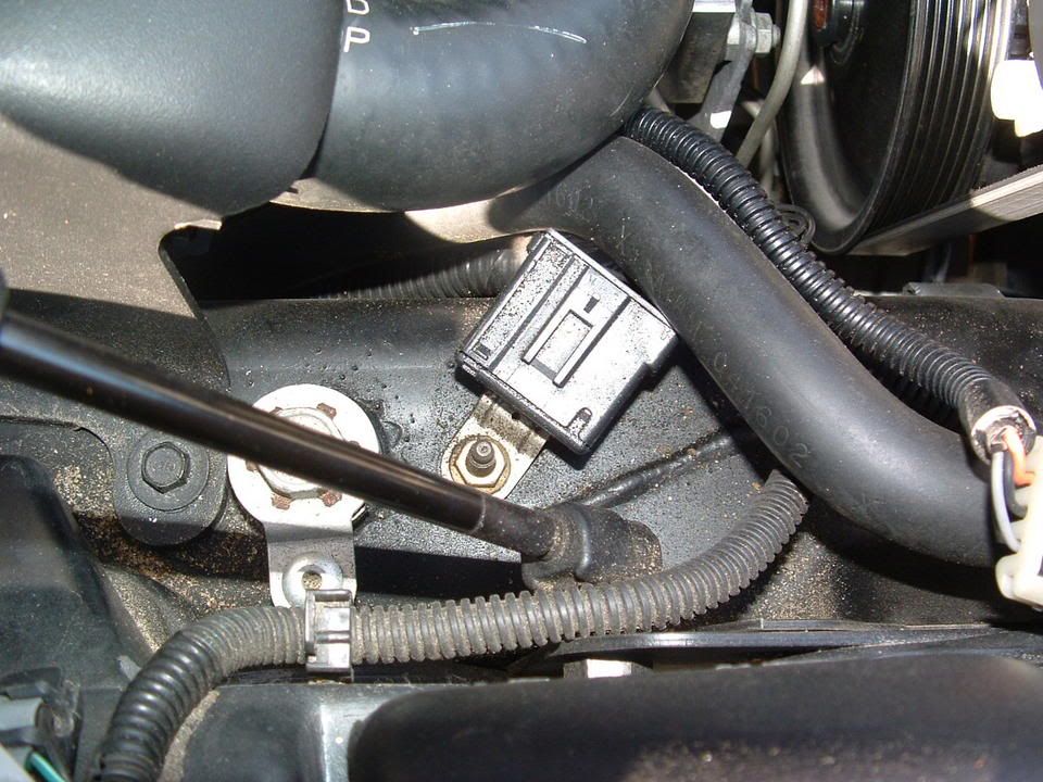
Corrosion inside connector! (You ain't seen nothing yet!)
[IMG]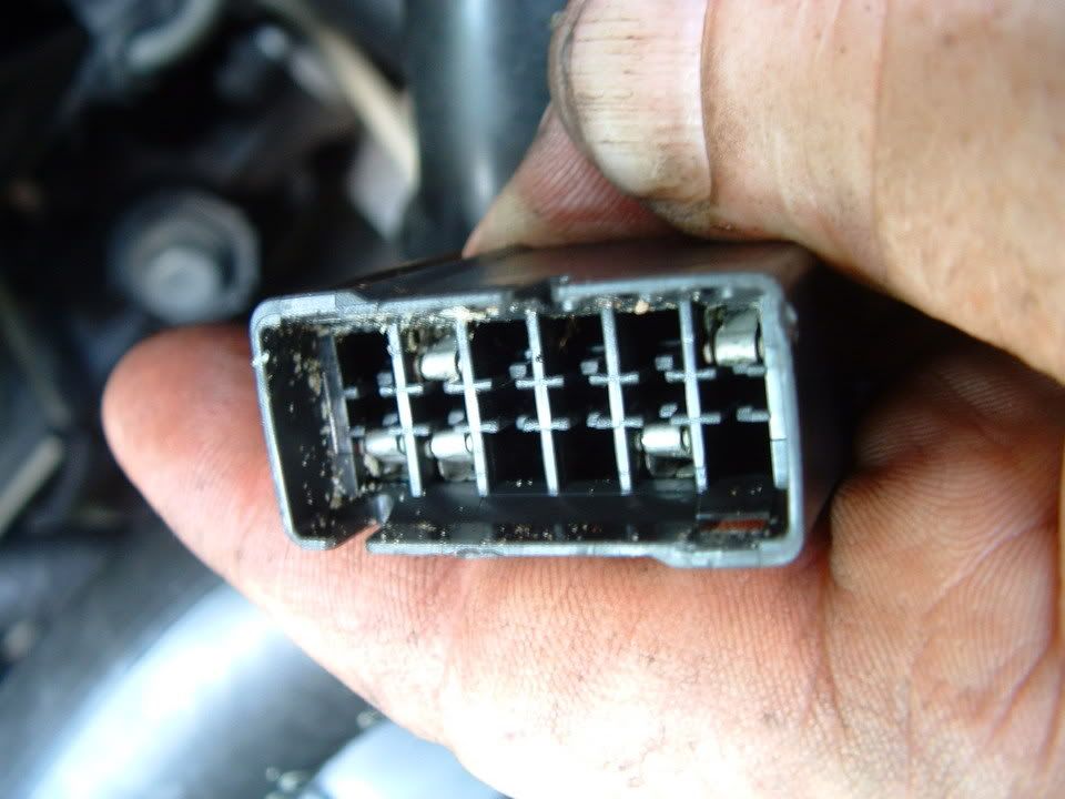 [/IMG]
Next three photos are of the corrosion found on the connector terminals!
[IMG]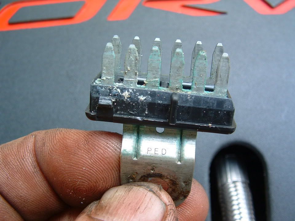 [/IMG] [IMG]
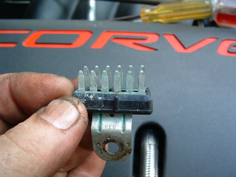 [/IMG] [IMG]
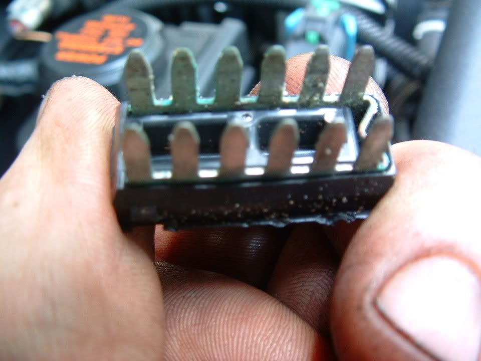 [/IMG]
Self tapping ground screw and star washer. This is what you will need if the ground stud breaks off during removal!
[IMG]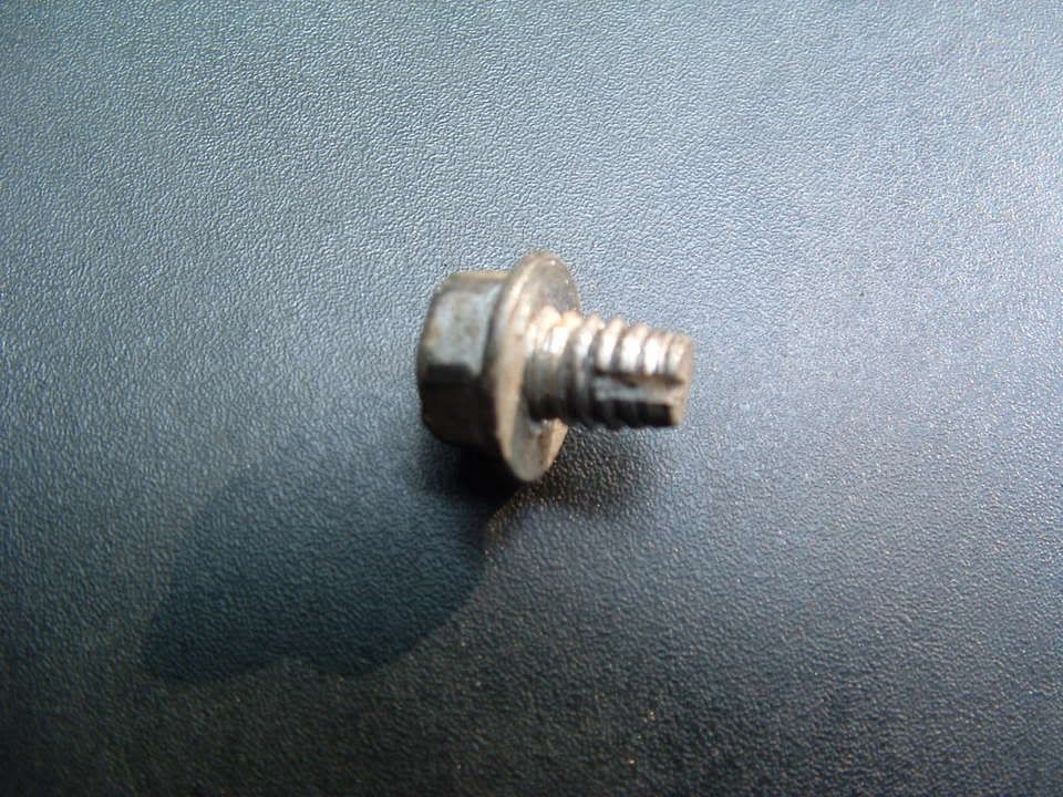 [/IMG] [IMG][IMG]
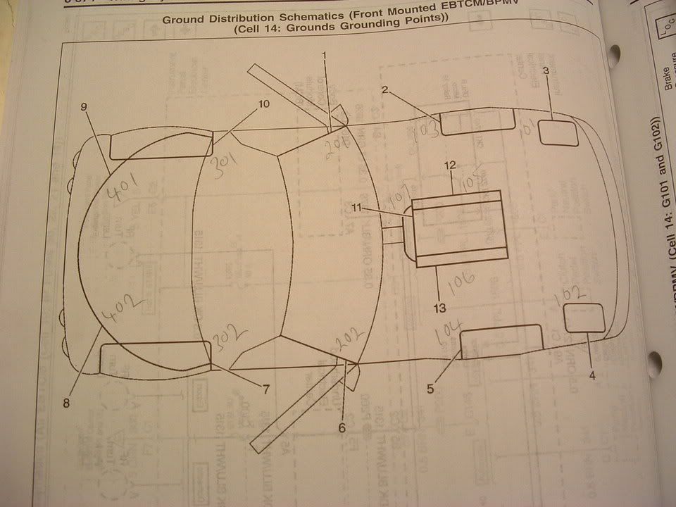
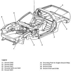
Here are where the chassis ground points are on a C5:

PLEASE let me know if you have any questions.
Bill Curlee
updated 02 March 06
My 98 coupe would get the infamous "REDUCED ENGINE POWER", "TRACTION CONTROL FAILURE" and a host of random failure codes. After many, many hours of troubleshooting, replacing the BCM and TAC module, I solved most of the driveability issues. Still getting the random DTC failure codes, I thought that I may be having ground issues. Back in June I cleaned ALL of the chassis grounds and the car virtually stopped throwing the "RANDOM" DTC failure codes. Just moving the wires in the chassis ground connector was enough to change the indications and make the issues stop happening.
I had a chance to speak with some GM C5 Trouble Desk Engineers when I went to Bowling Green KY in April and they pointed out that MANY of the C5 electrical issues can be directly linked to chassis ground problems. The engineer even went as far as to recommending that I chop off the factory under hood chassis ground connectors and combine all of the wires into a single ground lug. Not wanting to just LOP off the factory connector, I took a chance and disassembled one of the ground plug connectors and to my surprise it was indeed full of corroded connections.
I strongly recommend that any C5 owner that has had or who are having electrical issues, examine and clean the chassis ground connectors. This may save you from needlessly replacing expensive electronics modules. Each ground connector can be disassembled and cleaned in about 20 min.
Just cleaning the metal ground connection between the chassis and the plug is only a band aid solution. Now that I look back, when I cleaned my chassis grounds and initially solved my issues, I believe that when the connector is being removed to clean the connection between chassis and the connector, just the wires being moved inside the plug is what changed the indications and made everything work better.
Disassembly of the chassis ground plug and cleaning the contacts inside the connector is the correct method of solving the issue!
I took some pictures of the under hood chassis ground connector and the corrosion that was in it. I cleaned the two connections on the frame rails and the left one was significantly corroded! Taking it apart and cleaning it is a very straight forward procedure and I believe that if you follow this recommendation, you will be on the way to solving the many of the electrical issues.
Here are some detailed pictures of the ground connector and the corrosion that was found inside it!
Picture of under hood Chassis Ground connector G-101
Corrosion inside connector! (You ain't seen nothing yet!)
[IMG]
[/IMG] Next three photos are of the corrosion found on the connector terminals!
[IMG]
[/IMG] [IMG][/IMG] [IMG][/IMG] Self tapping ground screw and star washer. This is what you will need if the ground stud breaks off during removal!
[IMG]
[/IMG] [IMG][IMG]Here are where the chassis ground points are on a C5:
PLEASE let me know if you have any questions.
Bill Curlee
updated 02 March 06
Burning Brakes
Joined: Feb 2012
Posts: 901
Likes: 2
From: Palm City Fl
Crimped splices is a very POOR choice in a critical voltage circuit. Its VERY important to make a 100% ZERO resistance connection in that circuit and a crimp splice can not do that properly over a long period of time.
If it were me, I would replace the harness but,, properly soldering in a splice will work fine. Recommend finding some water proof heat shrink and using it to properly insulate the repaired areas.
Good luck Lt. Keep us informed on your progress.
Bill
If it were me, I would replace the harness but,, properly soldering in a splice will work fine. Recommend finding some water proof heat shrink and using it to properly insulate the repaired areas.
Good luck Lt. Keep us informed on your progress.
Bill
Burning Brakes
Joined: Feb 2012
Posts: 901
Likes: 2
From: Palm City Fl
Soldered all connections going to the TPS, covered in heatshrink, taped the harness and put it back in the plastic protective tube. I havent driven the car except to put it back in the garage. Again, I am not counting on that solving my problem as I could not get it to throw any codes while playing with all crimped connections with car running, prior to soldering the connections. I will be driving the car to work this week so will see how it goes and keep you informed. Many thanks for your time and input.
2nd UPDATE: Drove the car to work all week with no problems at all. Still not ready to declare victory, but I am pretty sure that the darn crimps were the whole problem. Why would a respected shop, an LPE dealer, and yes advertised here on the forum, use crimped splices on any electronic component??? I am truly at a loss...

3rd UPDATE: Declaring victory on the throttle Reduced Engine Power and Throttle Sticking issues. All seems to be fine now. Also today I removed my ECBM and resoldered the relay, no more ABS/TC/AH codes. Couldn't be happier. Thanks to all that have helped me solve these problems and learn so much about my car. Next I will be tackeling the wife's 99 coupe. Putting headers, high flow X pipe and the intake of my 02Z on it. Wish me luck. lol
4th & FINAL UPDATE: Declaring victory on the throttle issues. Thanks again for all the help Bill
Last edited by Lt. Dan M.; Dec 29, 2013 at 07:38 PM. Reason: 4th update